- 5 of Head Fixture (A3024HF)
- 1 of Implantable Lamp (A3024A)
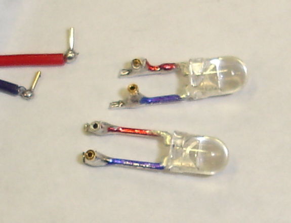
- 2 of White Test Lamps
- 1 of Command Transmitter (A3023CT)
- 1 of Booster Amplifier (ZHL-3A)
- 1 of 24-V Power Supply for Booster Amplifier
- 1 of Flexible Antenna with 2-dB Attenuator
- 1 of Telescoping Antenna with BNC elbow
- 1 of Coaxial Cable with 12-dB Attenuator
Early next week we plan to ship the following, which will complete the deliveries required by ISL Stage Three, Design and Construction of the Implantable Lamp.
- 4 of Implantable Lamp (A3024A)
In the photograph below, we see the Command Transmitter (A3023CT) connected directly to the Flexible Antenna. The 2-dB attenuator at the base is necessary to stabilize the A3023CT's power amplifier. This arrangement supplies 100 mW of 146-MHz RF power to the antenna, and is easy to set up. We use this arrangement for test that do not require us to operate more than 50 cm from the antenna. We determine the length, number, and spacing of RF power pulses using the same control program that we use with the Lamp Controller (A2060L).

The same photograph shows one Implantable Lamp (A3024A) flashing a white LED, and another at with a paper insulator around its L+ lead. The paper insulation is needed to stop the A3024A contact pins from touching when stored in a bag. If they touch and the lamp is stimulated, we will waste battery capacity supplying current to the lead resistance. The white LED is one of our White Test Lamps, which we have equipped with sockets to accept the pins on the tips of the A3024A leads. The test lamp leads have color codes and socket orientation to mimic the head fixtures and the colors of the A3024A leads.

When we want to operate farther from the antenna, and allow for random movements of the receiver, we add a ZHL-3A booster amplifier between the A3023CT and the antenna, and we use a telescoping antenna instead of the shorter flexible antenna. The telescoping antenna is more efficient. In this arrangement, we must be sure to insert the 12-dB attenuator between the A3023CT and the ZHL-3A, so as to protect the ZHL-3A's input from over-drive. With this arrangement, we obtain 100% reliable stimulation of the implantable lamps at range 1 m in our basement laboratory and 2 m in a faraday tent. This operating range is double that which we set as our target.

The telescoping antenna, being 1 m tall, needs to be vertical or else it will fall over. The ZHL-3A amplifier gets warm after a few minutes. We have found it to be rugged, but the manufacturer recommends that you connect its load (the antenna) and input (the cable carrying 146 MHz) before you connect power (the 24 V supply) in order to protect it from over-drive.
The Head Fixtures (A3024HF) are equipped with sockets for the A3024A contact pins. They are equipped with dummy cannulas in their guide cannulas. We have applied black epoxy over the clear epoxy that holds the fiber to the LED and the circuit board to the guide cannula. The black epoxy serves to mask light that escapes through the base of the fiber, which is roughly 85% of the light emitted by the LED. By masking this light, we are better able to estimate the power emitted by the fiber tip, and we avoid flashing a bright light into the subject animal's field of view, which might otherwise corrupt our experiment. The disadvantage of our black covering of epoxy is that the experimenter may not be able to confirm by inspection whether or not the implantable lamp is responding to commands. In future designs, we will consider placing a separate LED on the back of the head fixture to emit a small amount of light as an indicator for the experimenter.

It is hard to measure the total power emitted in all directions by the fiber tapers. Nevertheless, we tried to do so and obtained 2.5±1 mW. When we tested the fibers before we tapered them, we obtained 3±0.2 mW. These results are consistent, and suggest that the total power is a little below 3 mW. This 3 mW is well below our target of 10 mW. In the future, we will increase the power output at the tip by using a higher numerical aperture fiber, or higher drive current, or a more efficient LED, or some combination of all three modifications.
No comments:
Post a Comment