We applied 30 mA to a blue EZ290 LED and held a 10 mm × 10 mm photodiode 5 mm above fiber tip. We obtained a photocurrent of 1.2 mA, which corresponds to 6.0 mW of blue light. This seemed odd to us, so we repeated the measurement several times. This particular LED was emitting 18 mW at 30 mA, and our calculations based upon the fiber's numerical aperture suggested that no more than 3 mW should be emerging in total from the fiber tip.
We applied clear epoxy (E30CL) to the fiber base, with power still applied to the LED. The intensity of the light emitted by the tip of the taper decreased immediately, while that of the light emitted from the base of the fiber increased. We measured once again the power 5 mm from the tip of the fiber. We observed only 1.5 mW. Later, we measured power emitted in all directions with the same fiber tip and obtained a total of close to 3 mW.
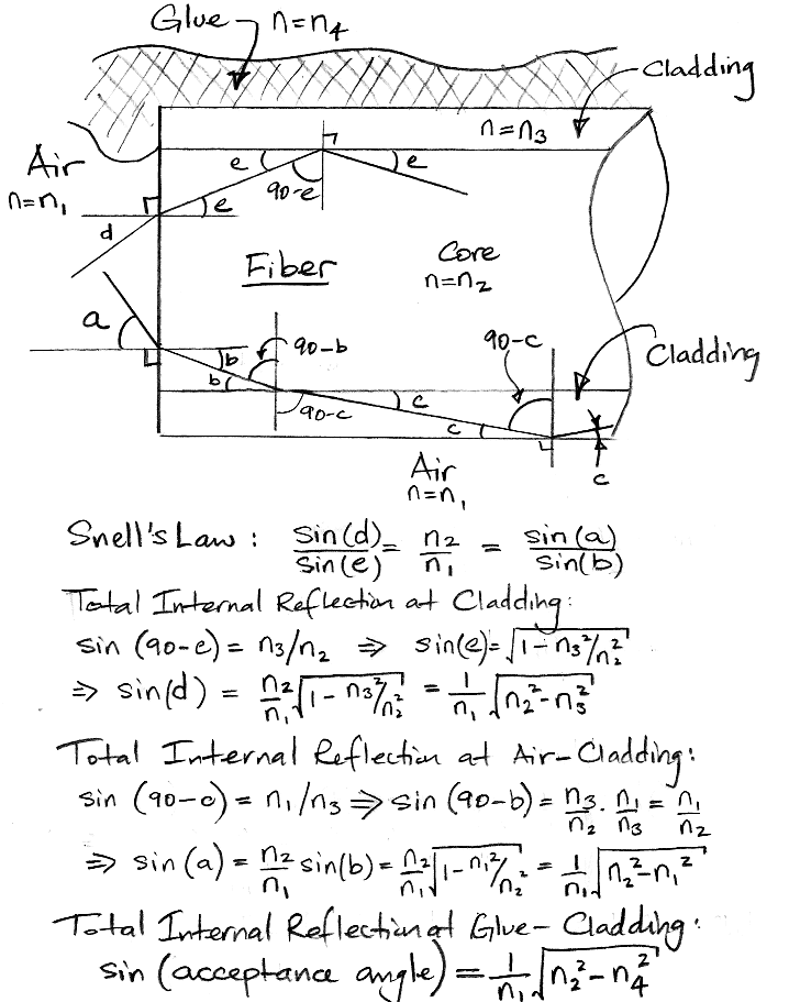
The numerical aperture of an optical fiber is the greatest angle a ray entering a polished, perpendicular face can make with the fiber axis and still be constrained within the fiber by total internal reflection. This total internal reflection can occur at the core-cladding boundary, which is always available, or at the cladding-glue boundary, or the cladding-air boundary. The following calculation shows how the numerical aperture of the fiber is affected by glue and air.

The WF300/330/P37 fiber has a cladding of fused silica, with refractive index n3 = 1.458. Its specified numerical aperture is 0.37, which is the numerical aperture we get by total internal reflection at the core-cladding interface. The refractive index of the air outside the base of the fiber is n1 = 1.000. Using the equation derived above, we conclude that the germanium-doped core of the fiber has refractive index n2 = 1.504. Now suppose we surround the fiber with clear epoxy. Our clear epoxy has refractive index n4 = 1.5. Because the glue has higher refractive index than the cladding, there will be no internal reflection at the cladding-glue boundary.
When we are assembling a head fixture, we hold the fiber in a clamp that touches the cladding along three contact lines each 5 mm long, so the majority of the cladding surface is exposed to air. Under these conditions, our equation gives us a numerical aperture of 1.1, which we interpret to mean that any ray entering the fiber will be trapped by internal reflection at the cladding-air boundary. Thus we expect to see all the power entering the base of the fiber emerging at the tip. Our fibers were not perfectly clean, so we were losing some light because of oil on the cladding surface, but we do see four times as much power when we hold the fiber without glue in a clamp.
Suppose we use a glue with a lower refractive index than the cladding. We will now see total internal reflection at the cladding-glue interface. Consider the MY132, UV-curing adhesive, designed specifically for cladding optical fibers. It is expensive (roughly $300 for 10 ml). But its refractive index is only 1.324. With this adhesive fastening the fiber to our LED, and coating the fiber up to the base of the taper, the numerical aperture of the fiber would be increased to 0.71, which means that light within a ±46° cone will be accepted and constrained within the fiber.
With numerical aperture 0.37, we expect to capture 14% of the light emitted by an EZ500 LED. This calculation is borne out by our measurements. But with numerical aperture 0.71 we will capture 51% of the emitted light. The power delivered to our fiber tip will increase by almost a factor of four.
We have learned from Cree that their EZ290 LED will not produce the optical power we expected. The most efficient LED we can buy is the EZ500. We believe the most efficient class of these LEDs will emit 30 mW of blue light with forward current 30 mA. A well-positioned 400-μm diameter fiber covers 90% of the light-emitting surface of the EZ500. Thus we can hope for 27 mW to enter our adhesive-coated fiber, and 14 mW to emerge from the tip. We plan to order a reel of the most efficient class of EZ500 LEDs, and a sample of the MY131MC adhesive, and test our hypothesis.
Another way to increase the numerical aperture of the fiber is to increase the refractive index of its core. We have ordered a sample of 1.4-mm diameter borosilicate glass rod from Fiberoptix, which has refractive index 1.6. We will try to stretch this to create a fiber of diameter 400 μm which, when coated by MY132, will provide numerical aperture 0.90 and therefore capture 81% of the LED light. We would then be able to deliver 22 mW to the fiber tip.
No comments:
Post a Comment