Friday, July 28, 2017

Grounding the Lamp Current

In Sources of Lamp Artifact we present our understanding of how lamp artifact of order 100-mVpp appears on the ISL's EEG signal when we flash the lamp. As we have reported before, this artifact is due to current flowing from the tips of the lamp leads, along the water-coated silicone insulation of the lamp leads, through the tunnels the leads make in the dental cement, and into the animal body. From there it flowed to the A3030C/D reference terminal for EEG monitoring.


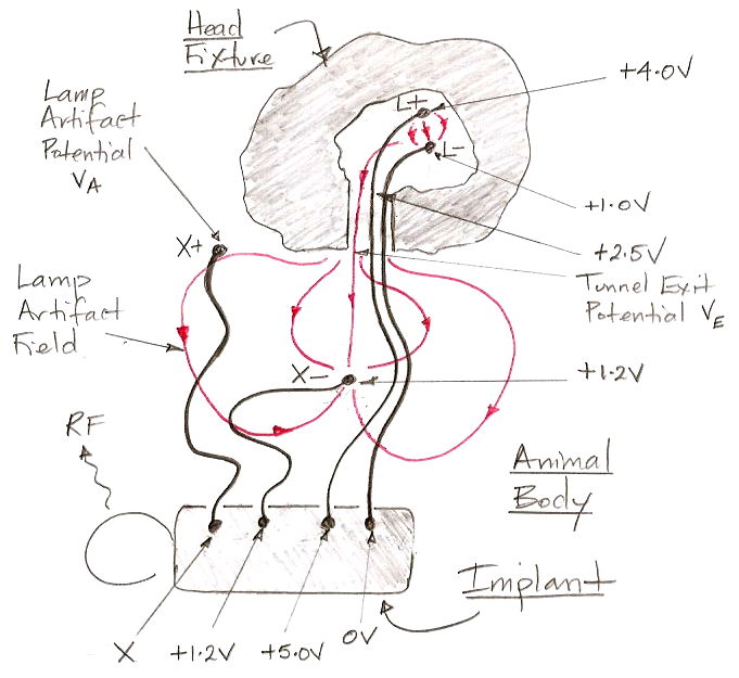
Figure: Lamp Artifact Current Flowing From L+ to X− When Lamp Is On. Voltages with respect to the implanted A3030D's 0V supply. Head fixture made of dental cement. Current in the leads is not shown.

We later tried the A3030D-LO, lamp-only version, with a Subcutaneous Transmitter A3028E to monitor EEG. We saw no lamp artifact in the EEG we recorded, as the following diagram attempts to explain.


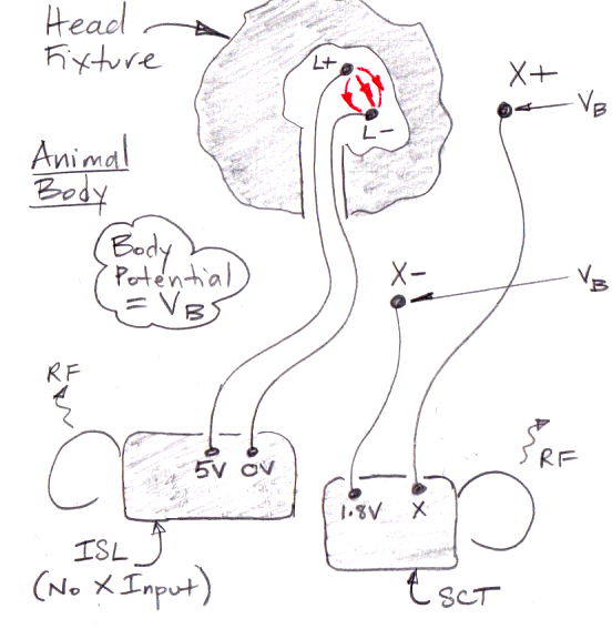
Figure: Separate SCT for EEG, ISL without EEG for Lamp. Head fixture made of dental cement.

One way to restore the ISL's own EEG measurement is to insulate the lamp leads with a ceramic collar, as we describe here. The ceramic collar makes is hard to explant and re-use an ISL because the solvent used to dissolve dental cement will also attack the adhesive we use to bind the silicone to the ceramic. The ceramic collar is arduous to assemble, and makes implantation of the head fixture more difficult. Furthermore, although we have tested the ceramic collar for fatigue resistance with machines and water here in our laboratory, we remain uncertain as to its reliability during a two-month experiment.

We propose to eliminate the ceramic collar. Instead of blocking the lamp current, we will absorb it with a coil of wire that enters the head fixture and wraps around the lamp leads. We will use a stainless steel compression spring for the purpose. For EEG detection we will use a differential amplifier in the A3030E rather than a single-ended amplifier. The current flow in the head fixture and animal we expect to be as shown below.


Figure: Grounded Seal Arrangement. Head fixture made of dental cement.

Our initial tests of this arrangement are promising. We await the arrival of the A3030E circuits, when we will be able to test the arrangement with a differential amplifier built into the ISL.

UPDATE: Here is a prototype grounding arrangement. A stainless steel spring is coiled around two lamp leads.


Figure: Grounding Spring Coiled Around Two Leads.

We can slide the spring up and down the lamp leads, but the lamp leads are pressing outwards against the coils. If the spring protrudes from the head fixture a few millimeters, it will provide a grounding point for our EEG measurement. Because it is wrapped around the lamp leads in the tunnel they make through the head fixture cement, the spring will absorb all lamp current that might flow through the tunnel.

Triple Helix Leads

Instead of a sealed ceramic collar to isolate EEG from lamp power, we propose for the A3030E to add a grounding spring around the lamp leads to absorb the lamp current that leaks out of the head fixture through the tunnels in the dental cement made by the lamp leads. Running to the head fixture we would have three leads: L+, L−, and GND. The GND is the ground connection. On the A3030E circuit, GND is connected directly to the 1.2-V power supply. We consider joining these three leads together in a triple-helix lead, as shown below.


Figure: Triple-Helix Leads. Top: 1 coat on individual leads followed by 2 coats on three together. Bottom: 2 coats on individuals, 1 coat on combination.

As we report here, these leads provide perfect electrical performance. But we find it impractical to prepare the ends for application of pins and a grounding spring. We must cut the wires apart and remove silicone from each tip without damaging the lead elsewhere. For now, we plan to stick with the well-tested individual wires, and hope that they do not take up too much space.

Lead Resistance Power Loss

So far, the ISL lamp leads for all versions of the A3030 device have been 100 mm, stretched MDC-13867A stainless steel springs with resistance ≈30 Ω. The buck converter on the A3030 supplies 5.0 V to one end of the lamp leads, the LED forward voltage is ≈3.0 V, leaving 2.0 V across the leads. Of the power delivered by the buck converter, 40% is lost in the lead resistance. In the past, we have tried to increase the maximum optical power emitted by the tip of the ISL fiber. We found that a 15 mW fiber-tip power could produce circling behavior with 2-ms pulses at 10 Hz. If we were to use 100-mm un-stretched leads, their resistance would be ≈60 Ω and fiber tip power would be 7.5 mW. We could then flash the light for 4 ms instead of 2 ms and emit the same number of photons, thus producing the same ontogenetic effect. The energy we lose in the lead resistance will be the same. In the A3030E, we propose to either increase the lead length to reduce strain on the head fixture, or to keep the lead length the same and use an un-stretched lead to achieve the same reduction of strain.