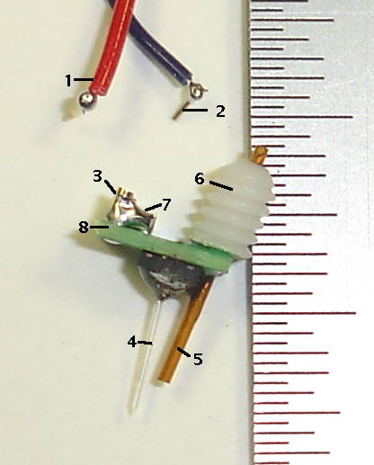
Part (4) is the fiber, one end of which is glued with clear optical epoxy to an EZ500 LED mounted on the circuit board. This fiber is a dummy we used to make a prototype head fixture. Its tip is sheared off at an angle instead of tapered with a flame.
Part (1) is the L+ lead from an Implantable Lamp (A3024A). Part (2) is the connector pin on the end of the L− lead from the same device. These pins plug into two sockets on the Head Fixture. Part (3) is the L− socket. The L+ socket is obscured by L−. Part (8) is the head fixture circuit board. Part (5) is a silica guide cannula. Part (6) is the threaded pedestal on the guide cannula. Part (7) is a smoothing capacitor to reduce noise induced in EEG recordings.
No comments:
Post a Comment