Friday, November 14, 2014

ISL Stage 5 Delivery

We ship to ION the devices shown below. There are five Implantable Sensors with Lamp (A3030B). These are encapsulated in acrylic, transparent epoxy, and clear silicone. They include command receiver, lamp power supply, EEG amplifier, and data transmitter.


Figure: ISL Stage 5 Deliverables. We have 5 Head Fixtures A3024HFC-B and 5 ISL A3030B. The ISL No2.1 is non-functioning. We see the two-turn command antenna bound up with the one-turn data antenna.

The lamp wires are 100-mm long. The orange lead is L+ and the purple lead is L−. Each pair of lamp wires presents resistance 65 Ω to the flow of lamp current, so that the current through a blue lamp will be close to 35 mA. The EEG leads are 150 mm long. The blue one is X+ and the red one is X−.


Figure: Implantable Sensor with Lamp, A3030B.

In addition to the five ISLs, we are sending five Head Fixtures (A3024HFC-B) with blue LEDs. These are No3.4, 3.5, 5.1, 5.2, and 5.2. They produce 13, 13, 13, 15, and 14 mW blue light respectively at their fiber tips when supplied with 40 mA forward current, as marked on their petri dishes. Our A3030B lamp current is 35 mA, so the light emitted by the fiber tips when connected to the A3030B will be around 12 mW.


Figure: ISL Controller Tool.

Accompanying these circuits, we have the ISL Controller Tool, Version 2.2, which fixes some device-addressing problems present in Version 2.1. Download the script and place it in the LWDAQ Tools/More folder to replace any previous version of the tool you may have installed.

Four of the five A3030Bs are fully-functional: No2.2-2.5. But No2.1 failed after water wash and encapsulation, along with our spare circuit, No2.6. In the future, we have to figure out how to load the battery and wash the solder joints to make the circuit clean, without damaging the lithium-ion battery, which is vulnerable to liquid water, and without causing the circuit, which has power attached, to enter a parasitic state that drains the battery quickly.

Before shipping, we used No2.2 to measure the effect of lamp flashing on the EEG amplifier. We will report on our observations in the next post.

Wednesday, October 1, 2014

EEG Monitor Incorporated

We have our first Implantable Sensor with Lamp (A3030B) with functioning EEG amplifier and transmitter. The circuit includes the same Command Receiver and Lamp Power Supply as the existing A3030A, but we have now loaded the amplifier, ADC, radio-frequency oscillator, transmit antenna, and electrode leads. In order to get the digitization and transmission working, we translated our existing data transmitter firmware from its original ABEL to the more modern VHDL required by the A3030B's CPLD. The graph below shows the frequency response of the amplifier as observed in the Recorder Instrument after digitization at 512 SPS, transmission at 902-928 MHz, and reception in by loop antenna in a faraday enclosure.


Figure: Amplitude versus Frequency for 11-mV pp input on X. We see the bump in gain at around 130 Hz, which is a characteristic of our three-pole Chebyshev low-pass filter.

We turn on and off the A3030B's 915-MHz radio-frequency data transmission with 146-MHz radio-frequency command transmissions. The A3030B is either digitizing and transmitting its analog input, or it is doing nothing with its analog input. We update the ISL Controller Tool to permit us to turn on and off data transmission with the press of a button.


Figure: The Updated ISL Controller Tool. We now have buttons Xon and Xoff to turn on and off data transmission. We have labels along the top that indicate the status of each of fourteen possible ISLs.

Of particular concern to us was interference between the data transmission and command reception. With data transmission turned on, there was the possibility of the 915-MHz power on the transmit antenna disrupting or stimulating the 146-MHz command receiver. But no disruption appears to occur. Command reception is equally effective with simultaneous data transmission.

We are also concerned about the effect of command transmission upon the A3030B's analog input. In an earlier experiment, we observed 20-mV pulses at the analog input in response to command transmission at range 70 cm. The A3030B includes a 40-kHz low-pass filter (R5, R6, and C here) at the analog input, which we expect to attenuate 146-MHz by a factor of 3500. In initial experiments, we are unable to observe any effect upon the analog input by command transmission. We will conduct more thorough measurements in the coming weeks. For now, with 100 μV of mains hum on our un-encapsulated circuit with external battery, we see no effect, so it appears that we have reduced its magnitude to less than 100 μV.

Only one A3030B exists today, which we made entirely by hand. We have ordered another thirty to be assembled by machine and shipped to us by the end of October. Of these, we will use 5, 5, and 10 to fulfill ISL Development Stages 5, 6, and 7 respectively.

Wednesday, September 17, 2014

ISL Stage 4C Delivery

We ship to ION the devices shown below. There are five Implantable Sensors with Lamp (A3030A). These are encapsulated in acrylic, clear epoxy, and clear silicone. They do not include EEG monitors, but they can be commanded individually, and instructed to perform extended optical stimuli with a single command. All five have 100-mm long stretched helical leads and through these they deliver 40 mA to an implantable lamp.


Figure: ISL Stage 4C Deliverables. We have (1) Rubber Duck antenna, (2) telescoping half-wave antenna, (3) Command Transmitter, (4) Head Fixtures A3024HDC-B, (5) Implantable Lamps Circuits A3030A.

There are five Head Fixtures (A3024HFC-B). All produce blue light. The power output from the taper tip at 40 mA forward current is written on the top of their petri dishes. Head fixture No3.1 produces 18 mW, which it obtains from a total lamp output of 34 mW. Its coupling efficiency is 53%, which is a little over our theoretical maximum, and 3.4 mW higher than our previous best head fixture. Another head fixture provides 15 mW. For more details see here.

The Command Transmitter (A3029A) is programmed to transmit serial commands to the ISLs. We plug LWDAQ power into its RJ-45 socket, and 24-V boost power into its power jack. We do not include a boost power supply in our ISL4C shipment. The boost power supply from the ISL4B shipment is still at ION, and will do the job. Note: we sometimes have to reset the LWDAQ Driver before the green power light illuminates on the A3030A.

We operate the Command Transmitter (A3029A) with our new ISL Controller tool, which you can download here. Place the TclTk text file in your LWDAQ Tools folder, or run it with the Run Tool option, and a window like the one shown below will pop up.


Figure: ISL Controller Tool in LWDAQ Software. The A3030A does not provide data transmission (Xon and Xoff).

The A3030A does not support randomized pulse generation. But it does support lamp dimming to 0%, 20%, 40%, 60%, 80%, and 100% of maximum intensity. The ISL Controller allows you to select the lamp intensity with a menu button. We can send the stimulus command to all A3030As or to an individual A3030A. We select channel 1-14 for individual devices, according to the serial number label on its battery.

We ship two antennas. One is a telescoping half-wave 146-MHz antenna. With this antenna we obtain reliable reception at ranges 0-1 m. The other is a short, flexible antenna (called a "rubber duck" antenna). With this one, we obtain reliable reception at ranges 0-50 cm.

We hope that ION's implantation of these devices will answer the following questions. Does the encapsulation resist condensation and corrosion? We have clear encapsulation to allow us to examine the devices after explantation. At what range is command reception reliable? What lamp power is required to provide stimulation, and what pulse length and frequency is optimal for stimulation?

We will visit ION on 16-OCT-14 to measure the operating range. In the meantime, we will start work on the A3030B, the same circuit as the A3030A, but with the EEG amplifier and data transmitter loaded.

Thursday, August 21, 2014

Corrosion of Lamp Circuit

Upon a visit to ION in July, we observed that lamp circuit No2.6 (with blue light) did not flash at all, and No2.1 (with green light) responds only with the antenna 10 cm from the animal. This was nine weeks after implantation. The head fixtures were still attached, the circuits were implanted, and the animals were healthy and active.

Now we have circuits No2.1 and No2.6 after removal from the animals, cleaning, and shipping to our office, and backing for 24 hours at 60°C. Circuit No2.6 does not respond to stimulus at all, but we poke through the encapsulation and measure 3.4 V on its battery, which is more than sufficient to power the circuit. Meanwhile, No2.1 responds well, with full operating range.

We encapsulated our A3024B-M and A3024B-R with clear, five-minute epoxy and then four coats of silicone. The silicone is about 1 mm thick all around. The epoxy coats the circuit and battery, making a better surface for the silicone to adhere to. We did not apply an acrylic coating to the circuit board, nor did we place the epoxy in a vacuum to remove cavities. There would have been little point in trying to remove cavities when the setting time of the epoxy was only a few minutes. After nine weeks implanted in large, healthy rats, the external silicone encapsulation of both devices is intact, and none of the leads show any sign of fatigue. But both circuits, within the unbroken encapsulation, are corroded. The photograph below shows corrosion on pins and pads carrying VBAT in No2.6.


Figure: Corrosion of Pins and Pads Carrying VBAT After Nine Weeks Implanted, A3024B-R No2.6. Click for higher resolution.

The battery voltage in the above circuit remains 3.4 V, but we cannot get lamp power out of the leads. The part on the left is U2, the boost regulator, and the part on the right is U1, the comparator. We see no trace of metal left in U2-6 or U1-5, the power supply pins for the two components. Meanwhile, circuit No2.1 now responds perfectly, with good operating range. But it, too, shows corrosion in the same location.


Figure: Corrosion of Pins and Pads Carrying VBAT After Nine Weeks Implanted, A3024B-R No2.1. Click for higher resolution.

In No2.1, we do see metal remaining in U2-6 and U1-5. The corrosion is a certain sign of condensation within the encapsulation, which we are familiar with from our subcutaneous transmitters. Condensation across R1, a 10-MΩ resistor, would reduce the resistance of R1, raising the device's power threshold, thus shortening its operating range.

UPDATE: [21-NOV-14] We encapsulated our Stage Four Implantable Lamps, of which No2.1 and No2.6 are two examples, in DP100 fast-curing epoxy. Its data sheet does not say that this epoxy corrodes copper, but other epoxies, such as DP270 state that they do not corrode copper, and so are recommended for encapsulation of electronic components.

Monday, August 11, 2014

ISL Prototype in Development

We are assembling and testing our prototype Implantable Sensor with Lamp (A3030). For details of development, see the manual. For circuit diagram, see S3030_1. The device combines an Implantable Lamp (A3024) with a single-channel Subcutaneous Transmitter (A3028B).


The A3030's logic chip contains enough programmable logic to implement a microprocessor, enough working memory to record several seconds of EEG, and enough non-volatile memory to retain its operating instructions. Our first implementation of the A3030 will provide only basic logic functions, such as decoding commands and generating trains of optical pulses. But in the long run, we plan to build a microprocessor in the logic chip. The A3030 provides a TQFP-100 footprint for the logic chip, which is 14 mm square. Future ISL devices will use the WLCSP-25, which is 2.5 mm square. Being a prototype circuit, we wanted to be able to make the A3030 by hand. The WLCSP-25 package is a 0.4-mm pitch BGA, which would be very difficult for us to load by hand.

The A3030's lamp power supply is almost identical to that of the A3024, except that it includes a switch to modulate the LED current at 5 MHz so as to dim the average power output without losing efficiency, and without producing any electromagnetic noise that would be picked up by our EEG monitor.

The command receiver uses the same split-capacitor tuning network as the A3024, except we now have a dual tuning diode to give us double the received signal amplitude. We hope this additional diode will increase the operating range of command transmission.

The EEG monitor is similar to the one in the A3028. It provides one channel with gain ×100 and cut-off at 160 Hz. To isolate the amplifier input radio-frequency noise and LED switching noise, we have a low-pass filter in front of the input, as we proposed earlier.

The A3030 has no magnetic sensor with which to turn on and off. We will switch it on and off with 146-MHz RF power through its Command Receiver. Each command transmission will activate, at least temporarily, all devices within range. After the command, some devices may remain awake, others may go to sleep, depending upon the commands transmitted. We will activate the EEG transmission through the Command Receiver also. The active current consumption of the A3030 with no EEG transmission and the lamp turned off is around 60 μA, which is much higher than the A3028's 20 μA and the A3024's 2 μA. This higher consumption is due to the higher-capacity logic chip.

The A3030 will be powered by a 382030 160 mA-hr lithium polymer battery. This battery is rechargeable, and we will be able to recharge it up until the time we encapsulate the entire device for implantation. After that, its value lies in its ability to delivery over 200 mA with minimal drop in output voltage.

Friday, June 20, 2014

Optogenetic Behavior Observed

Dr. Rob Wykes (ION, UCL, London) implanted two lamp circuits and head fixtures in adult rats on 16-MAY-14. Both the lamp circuits are the rat-sized A3024B-R.

In the first animal, he combined lamp circuit A3024B-R No2.1 with the green-light head fixture A3024HFB-G No2.12. This combination provides 6.4 mW at the tip of the taper. Using the cannula guide, he administered a viral injection of rAAV5/CaMKII-CHR(H134R)-mCherry.

In the second animal, he combined lamp circuit A3024B-R No2.6 with blue-light head fixture A3024HFB-B No2.6. This combination provides 14 mW of blue light at tip of the taper. He administered a viral injection of rAAV5/C1V1-TS-eYFP through the cannula guide.

The head fixture protrudes roughly 10 mm from the skull of the rat. Dr. Wykes enclosed the entire fixture, with the exception of the cannula guide thread, in dental cement. After five weeks, both animals are healthy, active, and the head fixtures remain in place. When the lamps turn on, we see the light clearly through the dental cement.

With the Command Transmitter (A3023CT), he flashes the lamps for 10 ms at 100 Hz. After two weeks, three weeks, and four weeks, there is no significant behavioral change in the rats when the lamp is flashing. Watching videos of the rats with the lamp flashing, it is possible they are curious about the reflection of the light off the walls of the cardboard box in which Dr. Wykes performs his tests.

Today, five weeks after the viral injection, both animals respond to the optical stimulation. They begin to turn in circles after around 15 s and after 60 s they have motor seizures.

UPDATE [21-JUN-14]: Dr. Wykes flashes the lamps for two-minute periods and observes behavior for various pulse lengths and frequencies. With the blue lamp, he observes circling for 2-ms pulses at 10 Hz. With the green lamp, 2-ms pulses at 10 Hz cause no behavioral change, 5-ms pulses cause circling, 10 ms pulses cause no behavioral change, and 20 ms pulses cause circling and seizure. With 10-ms pulses of blue light, 5 Hz causes no behavioral change, 10 Hz causes circling and motor seizure, 20 Hz causes no behavioral change, and 40 Hz causes some circling. With 10-ms pulses at a nominal 10 Hz, but with random displacement of the pulses, there is no behavioral change. The Implantable Lamp (A3024B-R) with a fresh battery can deliver 2-ms pulses at 10 Hz for 100 hours.

Wednesday, April 2, 2014

Fiber Bundle for Tethered Source Project

We became interested in designing a tethered system for delivering optical power to head fixtures. The possible advantages of a tethered system include indefinite experiment life, high light output, and low cost. This post assesses one way to make such a system and then proposes an alternative method. 

Concept


We plan to couple light into the optic tether by directly pressing the proximal end of the fiber against the surface of a bare LED, as we do with the ISL. The distal end of this optic tether will then be coupled to a short fiber taper that is implanted into the test subject's brain.

Our chief goal is to deliver a sufficient amount of light from the LED to implanted fiber tip. We could use the T5 glass used in the ISL, which has exceptionally high numerical aperture, but its high absorption makes it much better suited for short tapers than long patch cables. We've found that it is better to use glass with lower numerical aperture, but superior transmission; therefore we decide to use our "high index fiber" rather than "higher index fiber".

In direct coupling, optical power capture is proportional to the area of contact between LED and fiber. As we are interested in capturing about 30mW, we want to use a fiber with diameter over 400um. However, single fibers this large are not flexible enough for use as tethers in experiments. We contacted Fiber Optic Technologies and purchased several fiber bundles from them. Each bundle contains about 73 fibers glued to one another, each with 50um diameter. The numerical aperture of each strand is 0.66. The total bundle diameter is 500um, and the bundle is one meter long. The bundles we've purchased are packaged as patch cables; they are 1m long, coated in silicone, and each end is terminated in stainless steel ferrules. Being very flexible, these patch cables are physically suited for a tethered experiment.

We plan to connect one end of the patch cable to the LED, and connect the distal end to a head fixture with its own implanted fiber. The T5 tapers currently used in the ISL are a good choice for the implanted fiber since for distances less than 1cm, absorption losses are small. Since T5 has excellent numerical aperture, it should capture a large amount of light from the patch cable, and we have perfected the process of tapering this kind of glass to a sharp point.

We initially planned to use Cree's C460EZ500. Unfortunately, the bond wire of the EZ500 is pressed by the stainless steel ferrule of our patch cables, potentially causing a short. We could avoid this in the future with different ferrule choice, but for now, we continue our experiment with the blue Luxeon Z LED. The die of the Luxeon Z is a square, about 1mm on each side. Our sample is the blue version, 470nm. Optical power isn't specified for the 470nm die, but the manufacturer specifies 1050mW for the top bin 447.5nm version at its maximum rated continuous current, 1000mA.

For coupling efficiency from LED to fiber bundle, we expect the following losses:
500um diameter fiber bundle over 1mm x 1mm square die: 80.4%
10% gaps between individual fibers: 10%
13% of each fiber occupied by cladding: 13%
Numerical aperture of 0.66 limits the angle of the acceptance cone:  56%

We expect the amount of light to be captured by the fiber bundle to be 6.8% that emitted by the LED.

The next step in the tethered system is to couple this light into the T5 taper. Because the T5's numerical aperture is larger than that of the bundle, we expect all angles of rays to be captured. However, there is a mismatch in refractive index that will cause reflection. Examining the data sheets for F2 glass (used as the core of our patch cable) and P-SF69 (similar to the proprietary T5 glass in the core of our implantable tapers), we see that their refractive indices at 480nm are 1.6331 and 1.74158 respectively. This means that perpendicular rays will be subjected to 3.21% loss. At other angles, the reflection coefficient increases or decreases slightly depending on the ray's polarization. In this case, 3.2% is a good estimate for total reflection loss.

A larger loss will be incurred by the mismatch in diameters: the core of the T5 fiber that we intend to use is 420um, versus the 500um diameter of the bundle. This introduces a loss of 29.5%. The final form of loss is absorption, which we have measured to be 2.2% along a 10mm length. We expect 66.7% coupling efficiency from the bundle to T5 fiber. In total, we hope for 4.5% of the LED's light to emerge from the implanted fiber.

Experiment


We test our calculations by measuring optical power using an SD445, as described here. To avoid overheating the LED, we pulse it indefinitely for 1ms on and 19ms off. We observe a cleanly square signal of both the current passing through the LED and of the optical power produced, indicating that the LED is functioning normally and not being overheated. We drive the LED at its maximum continuous current rating, 1amp.

We measure 513mW optical power from the LED. Using a 3-D micrometer stage, we position the fiber bundle directly against the die in the position that gives maximum transmission. Power at the distal end of the fiber bundle is 41.5mW.  8.1% of the LED's light is coupled into the fiber, greater than the 6.8% we expected.

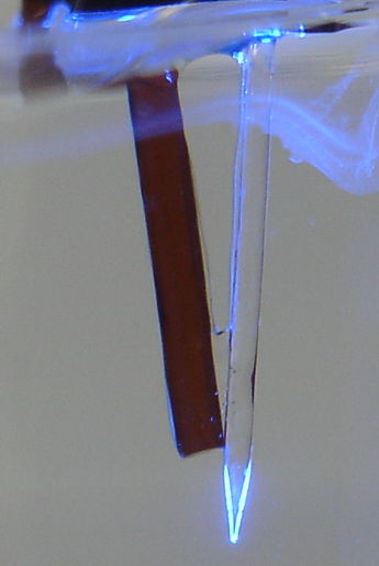
Next, we use a second micrometer stage to align a 141mm length of T5 glass against the distal end of the fiber bundle. The outer diameter of the T5 fiber was measured to be 0.45mm. We estimate its core diameter to be 420um. Both ends of the fiber bundle as well as both ends of the T5 glass are highly polished. We measure 17.6mW output from the distal end of the T5 section. From our knowledge of attenuation in T5 glass, we expect that 27% of the light initially captured by our 141mm section is lost due to absorption. In that case, the power initially captured in the T5 section is 24mW. The amount transmitted 10mm from the junction is 23.5mW. This is the figure we are interested in. Transmission from the bundle tip to 10mm down the T5 glass is then 23.5mW/41.5mW = 56.6%, lower than our anticipated 66.7% estimate. At this point along the T5 fiber, 4.6% of the light produced by the LED is present.

Fill Factor Estimation


We took photographs of the end of the patch cable with our microscope. The other end of the patch cable is being illuminated by the LED at low power so that we can visualize the optically active region of the bundle. This photo tells us that there are 73 functional fibers in the bundle.

Figure: Original photo of fiber bundle being illuminated by LED

There are multiple ways to estimate the percent of the fiber bundle's area which is occupied by core glass. We call this percentage the bundle's "fill factor". First, we can simply assume the nominal dimensions are correct. If the core of each strand is 50um and the total diameter is 500um, the fill factor is 73%.

Next, we could analyze the image directly using software. We convert the image to black and white using a thresholding operation, and count the white pixels to obtain a measurement of core glass area. We then measure the diameter of the bundle in pixels and calculate its total area. This method is sensitive to our arbitrarily selected threshold. Depending on threshold, we estimate fill factors between 57% and 69%.


Figure: The image is converted to black and white to count optically active regions of the bundle. The arbitrary selected threshold affects our estimate of fill factor. The two ends of the reasonable range of threshold values give 57% and 69% fill factors (left and right respectively).

Consider that the core diameter of T5 used in our experiment was 420um. If the fill factor of the bundle is 65%, then the power carried by the inner 420um of the bundle could have been replaced by a single strand with core diameter 340um. A single fiber of this diameter would likely be too stiff for experiments, so the bundle does represent an advantage over an optically equivalent single strand in this regard.

One way to improve light capture is to improve the fill factor. Glancing at the image, it appears possible to fit more individual strands into the same diameter bundle, though we don't know how difficult it would be for our supplier to accomplish this.

Alternate Methods


In the course of our experiment, we found that the Luxeon Z could be over-driven without apparent damage. For a current of 1.3A and 1ms pulses, the LED produced 17% more light than at 1A. Operating in this mode would produce 27.5mW at the implanted fiber's tip, but long term effects on the LED are unknown, and accidentally leaving it on continuously at the high current would likely damage it.

There may be a better way to make tethered LED hardware altogether. Plexon advertises LED units on their website. They advertise 24.9mW for their blue LED (465nm) at the end of a 1m long, 200um core fiber, NA= 0.66.  They indicate that this power can be sustained continuously and can be increased for low duty cycles (over driving the LED). This is a large amount of light for such a small fiber. Unless Plexon uses LEDs with much higher luminous density than any that we're aware of, we don't believe this kind of result is possible with direct coupling. Perhaps their system uses a lens to focus the LED's light to achieve this impressive result. In the past, we'd discounted this option, since it is impossible to focus a Lambertian source to a point smaller than itself with simple lenses. Perhaps this isn't necessary, however. One could design a focusing system with the admission that only rays sufficiently parallel to the diode will be captured. For a large LED such as the Luxeon Z, this might work well. The wide angle rays from the LED may be lost, but we'd be able to capture all sufficiently parallel rays from its large 1mm square surface. These rays could be focused into a spot small enough to couple light into a 200um core fiber as Plexon may have done. Through our alignment projects in physics experiments, we have experience aligning laser diodes with lenses to focus light into fibers. Our system could be adapted to work with LEDs. Note that a 200um core single strand would be suitably flexible for experiments, making the bundled approach unnecessary.

Plexon's published results also tell us something about the efficiency of transmitting light from one multimode fiber to another. In our experiment, we observed 57% efficiency in coupling from the fiber bundle into the T5 fiber when we expected 67%. This indicates a 15% unexplained loss. This unexplained extra loss may be the result of the geometry of the fibers within the bundle (perhaps the local fill factor - directly beneath the T5 fiber's core - was smaller than the total fill factor). However, it seems more likely that it is due to an effect that we haven't yet identified, such as extra reflections.

Plexon may also be experiencing this mysterious loss; of 24.9mW at the end of a patch cable, they couple 19.9mW into a fiber stub of the same diameter (and presumably same fiber). In our model, the transmission efficiency between identical fibers is 100%, so their 20% loss is surprising. This loss at the fiber-to-fiber junction mirrors the loss we observe in our experiment, and could be due to the same source, (extra reflections?). In future work, we should keep the possibility of 15-20% fiber-to-fiber loss in mind.

Conclusion


With the blue Phillips Luxeon Z LED mounted on a heat sink, a 1-m flexible fiber-optic bundle, and a 10-mm implant fiber, we can deliver 23.5 mW continuously to the brain of an animal.

Monday, March 10, 2014

Performance of Chamber for IVC Rack

On 05-MAR-14, in the new animal room on the tenth floor at ION in London, we test reception in an IVC rack with and without the radio-frequency isolation chamber shown below. Each cage is for one or more mice, and has a metal grating to hold food pellets under the lid.


Figure: IVC Rack with Isolation Chamber. We have a sheet of copper taffeta fabric on top and bottom. Behind and to the sides are walls of AN-77 absorbers backed by aluminum sheet. In front is a curtain of steel mesh fabric. Antennas are at locations marked "X". Cage labelling scheme as marked on the rack.

We place the eight antennas of an Octal Data Receiver (A3027B) between the floors of cages B7-F7 and B6-F6. We measure reception in the rack by removing one cage and rotating and translating an subcutaneous transmitter (A3019D) on the end of a stick for one minute within the volume the cage would have occupied. We record the fraction of messages received. When the curtain is in place, we cut a hole in the curtain and pass the stick through the hole. Before we install the isolation chamber, we measure the reception in cage spaces as follows: E7 = 92.5%, E6 = 99.2%, E5 = 96.7%, F7 = 85.1%, B7 = 91.6%, E7 = 91.8%, D5 = 99.6%. After we install the isolation chamber we get: E7 = 100.00%, F7 = 100.00%, H1 = 100.00%.

Without the chamber, reception is not quite good enough for reliable recording, even within 30 cm of two antennas. With the chamber, reception is 100.00% reliable everywhere.

Friday, February 21, 2014

Stage Four Delivery

We have five head fixtures and five implantable lamps ready to ship to ION. Shown below are 3 of A3024B-M (mouse-sized) and 2 of A3024B-R (rat-sized) implantable lamp with lithium-ion battery. Each circuit is encapsulated in clear epoxy and four coats of silicone. Each lead is terminated with a 300-μm diameter gold-plated pin. The red lead is L+ and the blue is L−.


Figure: ISL Stage Four Delivery of Implantable Lamp Circuits, A3024B-M and A3024B-R. The blue line is 50 mm long.

The operating range of these lamps for command reception in our basement office is at least three meters. But one of our concerns with the mouse-sized A3024B-M is the size of the antenna, combined with the short length of the leads. We are not sure how the surgeon can implant this device in a mouse with the antenna maintaining its shape and the leads reaching the skull. If the surgeon finds that there is insufficient space to accommodate the antenna as it is, he should feel free to deform its shape. Deformation of the antenna will reduce operating range for command reception, but we expect the range will still be over 100 cm.

The table below lists the characteristics of each lamp. We estimate the transmitter volume from caliper measurements. We charged the batteries just before encapsulation. We measure the lead resistance with a meter. The current delivered by a lamp circuit is limited by the resistance of its leads. Lamp circuit No2.4 has two solder joints in its leads at the base, where we replaced unstretched leads with stretched leads to allow the circuit to deliver more current.

Circuit
Number
Battery
Capacity
Body
Volume
Lead
Length
Lead
Type
Lead
Resistance
2.1160 mAhr4.8 ml100 mmStretched56 Ω
2.219 mAhr1.7 ml50 mmUnstretched55 Ω
2.319 mAhr1.7 ml50 mmUnstretched55 Ω
2.419 mAhr1.7 ml50 mmStretched29 Ω
2.6160 mAhr4.8 ml100 mmStretched56 Ω
Table: Characteristics of ISL Stage Four Implantable Lamp Circuits.

The photograph below shows one of five A3024HFB head fixtures. There is some deliberate variation in the way we aligned the fiber tip and the guide cannula. Click on the head fixture names to get a close-up picture of each one. In all cases, the fiber's outer diameter is close to 450 μm. The head fixture shown below is No2.11, an A3024HFB-G green lamp. Note that the glue does not extend to the contact between the guide cannula and the taper. In some head fixtures, the contact point is glued, in others it is not. In the former, we are sure there is no glue on the taper. In the later, we know that the guide cannula is fragile. We are also shipping A3024HFB-B No2.4, 2.9, 2.6, and A3024HFB-G No2.12. All are equipped with two sockets that accept 300-μ diameter pins. the L+ connection is marked "+" on the circuit board, and the L− connection is marked "−".


Figure: ISL Stage Four Head Fixture A3024HFB-G. The guide cannula is 15 mm long, and designed for a 22-gague needle. It is PlasticsOne part C313GS-4-FS-SP. The cannula ends 9 mm below the pedestal.

The characteristics of each head fixture are given in two tables for the blue and green versions. Any implantable lamp may be combined with any head fixture. By choosing which lamp circuit to combine with which head fixture, we can obtain more or less power at the fiber tip, and more or less operating life. The following table shows some example combinations.

Circuit
Number
Battery
Capacity
Lamp
Number
Light
Power
Light
Color
Lamp
Current
100% Duty
Life
10% Duty
Life
2.419 mAhr2.422 mWBlue70 mA5 min2 hrs
2.6160 mAhr2.126 mWGreen40 mA2 hr20 hrs
2.219 mAhr2.913 mWBlue42 mA10 min3 hrs
Table: Light Output and Operating Life of Various Combinations of Lamp Circuits and Head Fixtures.

If the capacity of a lithium-ion battery is C mA-hr, it can deliver up to C mA continuously while delivering its full capacity. At higher currents, its capacity decreases. But if it is allowed to recover after short bursts of higher current, it can deliver close to its full capacity. We present discharge graphs for our lamp circuit batteries here.

According to Bernstein et al., "To activate channelrhodopsin-2 and halorhodopsin molecules in mammalian neurons requires light of the appropriate color at a radiant flux of 10 mW/mm2 or greater, for maximal activation. A radiant flux of 1 mW/mm2 will activate approximately 50% of the molecules, and a radiant flux of 0.1 mW/mm2 will activate very few of the molecules." Light power density will drop with range from our fiber tip due to the geometric inverse square law, scattering, and absorption. Scattering causes power loss only because it encourages absorption by increasing the effective path length from the fiber tip. According to Johansson, the absorption coefficient of brain tissue is 0.35 mm−1 at 460 nm and 0.25 mm−1 at 527 nm. The scattering coefficient is around 1.2 mm−1 for both wavelengths.

Along a 1-mm path in the brain, 70% of photons will be scattered. Most of them will travel around 1.5 mm to arrive 1 mm from their starting point. Along this 1.5 mm path, 40% of 460-nm photons and 30% of 527-nm photons will be absorbed. If we consider a hemisphere around the base of our fiber tip, of radius 1 mm, its area is 2π mm2. If the fiber tip emits 13 mW of 460-nm light, the intensity on the surface of this hemisphere will be of order 13 mW / 2π mm2 × 60% = 1.2 mW/mm2. For 6 mW of green light we get 0.67 mW/mm2 at the same range. Our calculation is optimistic in that we assume the light is confined only to a hemisphere, but pessimistic because it ignores the fact that the light is being emitted all along the fibre tip, so the path length of most photons to the hemisphere surface will be shorter than we have assumed.

Thus we believe that our head fixtures can deliver over 1 mW/mm2 of 460 nm light and over 0.5 mW/mm2 of 527 nm light at a range of 1 mm from the fiber tip, and that this intensity will be sufficient to excite a significant proportion of opsin molecules in a 1-mm hemisphere.

Thursday, January 9, 2014

Taper and Guide Alignment

We receive 9-mm guide cannulas from Plastics One, part number C313GS-4-FS-SP. Following a discussion with Dennis Kaetzel last year, our plan is to glue the tip of the guide cannula to the base of the taper, so that they are joined, in contrast to our original head fixture design, where the guide cannula was pointing towards the taper but not attached to it.

The 9-mm guide is too long for head fixture A3024HFB No2.2, so we sand it down with 15-μm grit paper until it looks right. We glue it in place with five-minute epoxy. We manage to avoid blocking the guide cannula with glue, nor do we see any glue on the taper. The guide cannula and the tapered fiber are shown below, immersed in water, and emitting blue light.


Figure: Head Fixture No2.2. We sanded the 9-mm guide cannula down to a length of roughly 8 mm so that its tip would be adjacent to the base of the taper. The outer diameter of the fiber is 450 μm and of the guide is 700 μm. The misty blue light in the upper foreground is an artifact of the plastic petri dish between the water and our camera.

There are three ways to define the base of the taper. One is the physical base, where we first observe curvature of the outer glass. This is the definition we used when gluing the guide in place. We also have the point along the taper that first emits light when the taper is in air, and when the taper is in water. The taper emits light earlier in water than in air. The brain is mostly water, so we immerse the taper in water for the photograph above. The guide cannula ends 0.3 mm before the emission of light, and the emission of light is 1.0 mm from the tip of the taper, as measured along the fiber axis. Thus the light-emitting length of the taper in water is 1.0 mm.

Which is the best place to have the end of the guide cannula? At the physical taper base, or the water-emission taper base?

UPDATE: [27-JAN-14] Head Fixture No2.5 looks like this in water. The end of the guide cannula is 450 μm from the end of the taper, light-emitting length of the taper in water is 1000 μm.

UPDATE: [31-JAN-14] Head Fixture No2.7 looks like this in air. The end of the guide cannula is 600 μm from the end of the taper, light-emitting length of the taper in air is 700 μm.