Monday, October 24, 2016

Lamp-Only ISL

In our experiments with implanted ISLs, the A3030D has been plagued by lamp artifact caused by water carrying the lamp voltage out of the head fixture and into the animal body, where it corrupts the EEG signal. Ceramic dual-bore collars around the lamp leads stop the water conduction, but the seal within the collar can still fail, and when it does, the EEG signal is compromised. The A3030D-LO is designed to remove the concern of seal failure from an optogenetics experiment by removing the EEG pick-up leads alltogether. We combine the A3030D-LO with a separate subcutaneous transmitter to monitor EEG. The EEG and lamp power circuits are now separated and their battery power supplies are floating with respect to the animal body. Failure of the collar seal will introduce some artifact into the EEG signal, but two orders of magnitude less than if the EEG X− lead is connected to the lamp power 0 V at the same time the seal breaks.

We take two A3030Ds, D7.11 and D7.6, and dismantle them both. We remove their batteries, antennas, lamp leads, and sensor leads. We load new sensor leads with collars and new antennas. We do not load EEG leads. The result is the A3030D-LO, the Lamp-Only version of the ISL. The EEG amplifier is still operational. The device will transmit data and acknowledgements.


Figure: Implantable Sensor with Lamp, Lamp-Only Version (A3030D-LO).

We take care to make sure the pins are soldered in the correct direction on the leads. Looking at this picture we see that the positive (orange) lead must be in the foreground when the pins are pointing to the left. Otherwise the implanter has to rotate the pins. The length of lead from the collar to the pin is 5 mm so the implanter will not need to fold the leads within the head fixture, but instead can build the head fixture directly over the pins and collar. The devices are encapsulated in black epoxy using our rotator procedure, and then coated in SS-5001 silicone, with extra silicone applied to the sharp corners. The result is not pretty, but it is resilient and flexible.


Figure: A3030D-LO Lamp Artifact, 10 ms pulses.

The figure above shows the artifact we see on the disconnected EEG signal when we flash a white LED with a 40-mA lamp current at 100% brightness. We will ship these two devices to ION/UCL this week.

Wednesday, June 22, 2016

Differential Input and Dual-Bore Collar

When we add collars to our ISL lamp leads, the collar seals last no more than a week before they break and a >30 mV lamp artifact appears. In our most recent implantation, we buried the lamp lead tips in dental cement with their collars, but without a lamp. Immediately after surgery, we observed full-scale lamp artifact, which suggests one or both seals broke as soon as the animal started to move.

We have difficulty adding collars to existing lamp leads because the leads are too thick to pass into the collar bore. We must stretch the leads by their steel wires, which compromises the elasticity of the insulation and causes the end of the lead to curl up. We now start with new lamp leads, with tapering insulation at one end, and thread these into dual-bore collars. We cut off the existing lamp leads and solder the new leads in place.

The ISL's EEG amplifier has a single-ended input. It measures the potential difference between the X+ and X− electrodes, but the X− electrode is a direct connection to the 1.2-V power supply in the ISL circuit. When the lamp lead collar seal breaks, fluid around the leads connects the surface of the skull to 5 V. The point connected to X− remains at 1.2 V. Current flows from 5 V to 1.2 V. The point connected to X+ is somewhere in the potential field generated by this current, and so we have the lamp artifact. If our ISL amplfier were truly differential, and presented a 10-MΩ impedance at both X+ and X−, the current flow to the X inputs would be greatly reduced. We would, however, still need a reference connection somewhere in the body to anchor our differential amplifier's input range, and this reference connection would re-create the problem we started with. But if we use a floating power supply for our differential amplifier, such as is provided by an indepenent SCT device, we get the near-perfect differential input without any need for a reference connection. In this way, we may be able to reduce the artifact arising from broken seals dramatically.

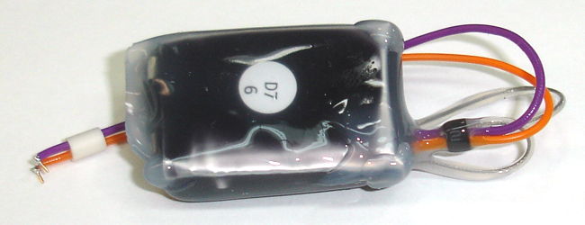
Our plan is to test the dual-bore collar and the floating differential EEG input in a single experiment. We have A3030Ds D7.9 and D7.11 modified as shown below, and ready to ship with (
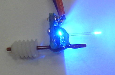
A3028E) numbers E116.7 and E116.12. We attached new lamp leads and insulated the joints with silicone. The lamp leads pass through a dual-bore collar, into which they are glued with Ultragel. We have a blue LED soldered to the ends of the lamp leads. We cut off the EEG leads and covered with silicone. The A3028Es have a pin and a bare wire for electrodes, but the choise of electrode is unimportant.


Figure: ISL and SCT Lamp Artifact Devices.

The circular A3028E has 10-MΩ input impedance and will measure lamp artifact with a power supply independent of the ISL. We have not joined the EEG leads along their length, thus reducing their sensitivity to magnetic fields, because at this point we know the >1 mV lamp artifact is generated by electrical conduction through water around the lamp leads, not by the lamp lead's magnetic field. The ISL itself measures only the internal electronic lamp artifact of the ISL circuit. Its EEG leads are cut off and sealed.

We put our two ISLs in water and start them producing 10-ms pulses at 10 Hz. We record their EEG input with the LEDs out of the water and with the LED in the water.


Figure: Two ISLs Flashing, Insulated EEG Leads. Left: lamp out of water. Right: lamp in water.

We put the two SCTs in the water and measure artifact with the LEDs out of the water and in the water.


Figure: One ISLs Flashing, Two SCTs in Water. Left: lamp out of water. Right: lamp in water.

With the lamp in the water, we have the No7 (salmon) EEG pick-up electrodes 10 mm from the exposed terminals of the LED, an the No6 (brown) electrodes are 40 mm away. In the 40-mm case, if we were to use the ISL's own amplifier, we would see artifact of >27 mV. With our floating EEG input we see roughly 3 mV. We ship these components to ION. If the collar seals are effective, we should see less than 100 μV artifact on the SCT amplifiers. If the collar seals break, we should see something between 100 μV and 3 mV artifact, depending upon the resistance of the fluid that penetrates the collar.

UPDATE: [09-AUG-16] We implant ISL D7.9 and SCT E116.7 at ION/UCL. The ISL's EEG leads are cut short and sealed. The SCT EEG electrodes are on the skull. The ISL's LED is embedded in a dental cement head fixture, with the dual-bore collar within the cement. Six days after implantation we see the following artifact during lamp stimulation.


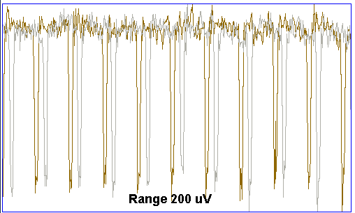
Figure: Lamp Stimulation Artifact with Brightness, Simultaneous in SCT and ISL. Six days after surgery. Pulse length 20 ms, interval 50 ms, 200 pulses. Left: from SCT E116.7, right: from ISL D7.9.

The artifact in the ISL reaches a maximum at 40% brightness, which is a characteristic fo the electronic artifact generated within the ISL circuit. Its amplitude is of order 100 μV. There is no sign of artifact in the SCT recording. We look at the spectrum of the SCT signal over eight seconds during 100% brightness and see no sign of a peak at 20 Hz (50 ms period), which means the lamp artifact in the SCT recording is <10 μV.

We implant D7.11 and E116.12 in another rat. This time, the EEG leads of the ISL are cut short but not sealed, so that the wire tips are several millimeters apart in the abdomen and exposed to body fluid. Two hours after implantation we observe the following lamp artifact.


Figure: Lamp Stimulation Artifact, Simultaneous in SCT and ISL. Two hours after surgery. Ten pulses of 10 ms, interval 100 ms. Red: from SCT E116.12, Gray: from ISL D7.11.

The artifact in the SCT signal remains <10 μV. But the artifact in the ISL signal is of order 20 mV. If the collar seals were to break, current would flow from the head fixture to the ISL's X− input, which is connected to the ISL's 1.2-V power supply. A potential field will develop through the animal's body. The SCT electrodes on the skull, being of order 10 mm apart, will pick up this pulsing potential field, as will the ISL's X+ electrode, which is a few millimeters from X−. But we see no artifact in the SCT EEG, so the artifact cannot be caused by a break in the collar seal. Instead, we suspect that the seal around our lamp lead solder joints has failed after minimal fatigue or handling, and the result is a pulsing current between an exposed lamp power lead and the ISL's X−. The ISL's X+, being nearby, picks up this field, but the SCT's EEG electrodes, being far away on the skull, do not pick it up.

Tuesday, March 15, 2016

Lead Flexing Machine

We have four single-bore ceramic collars cemented with silicone to four leads. The two small collars are 1.0 mm ID (inner diameter), 2.3 mm OD (outer diameter), and 3.2 mm long. They will slide over leads with only three coats of silicone. The two large collars are 1.7 mm ID, 4.3 mm OD, and 4.8 mm long. They slide over any lead. Both beads have a concave side and a convex side. We slide the lead into the concave side. We coat the lead with silicone and slide in and out until we see silicone on the lead on both sides of the bead. The concave side holds a body of silicone around the lead. We hand to cure. The results are shown below.


Figure: Single-Bore Ceramic Collars. The gray marks on the collars show where we have scraped silicone off the outer surfaces.

Once cured, we note that silicone has crept half-way up the outside of the collars. We scrape the silicone off with a scalpel. Cut cut the short ends to the same length, remove 2 mm of silicone to expose the wires, and cement into a tub of dental cement all together. We place in water and set up a motor-driven wire-flexer that pulls on the leads while they sit in a beaker of water. We clamp the leads 50 mm from the collars and we streth them by 10 mm once per second.


Figure: Wire Flexing. We are measuring isolation of the orange lead while flexing all four leads by 20% once per second.

After thirty seconds, we measure isolation resistance of each lead with respect to the water in which the cement fixture is immersed. For the blue, red, and purple leads, the isolation is only 1 MΩ, indicating the seal between the silicone and ceramic has broken. We are seeing the resistance of the microscopic film of water between the lead and the collar. The orange lead's isolation is >100 GΩ. We put the cement fixture in our ove at 60°C. After half an hour, we place in water again and isolation resistance is >100 GΩ for all four leads. We begin flexing. Within thirty seconds, isolation resistance is 1 MΩ for blue, red, and purple. The isolation of the orange lead remains >100 GΩ after 3600 s of flexing.

The fit between the lead and the collar in the previous four examples was tight only in the case of one of the smaller collars, although we did not make note of whether it was the orange or the purple. The only way to make the fit tight is to start with a lead of tapering thickness. We have eight such leads. We make four tight-fitting collars with silicone as adhesive and leave to cure in warm humidity. Another possible source of failure in the collars we glue in place with silicone is failure of the seal outside the collar because of silicone residue on the ceramic surface. We make another four and glue with Loctite Ultragel. We allow the glue to cure in warm humidity for one hour. We assemble into a dental cement head fixture and load into the wire flexer. We connect all four free ends of the leads together to our isolation meter. All four isolation resistances in parallel are 3 GΩ. After 600 s, combined isolation is 4 GΩ. After 5000 s, it is >100 GΩ. We leave the flexer running.

UPDATE: [16-MAR-16] After 18 hrs of flexing, leads 1-3 of our set of 4 have broken by fatigue where they pass over the lip of the beaker in our wire-flexing apparatus. Lead 4 is intact, with isolation resistance >100 GΩ. We remove silicone from the free ends of the other leads, and isolation resistance is >100 GΩ for all three. In one case, we have 65,000 flexes and the collar seal is still intact. In the other three cases, we have failure of the spring by fatigue before the collar seal fails by fatigue.


Figure: Four Surviving Collars. Leads 1-3 broke by fatigue some time between 5k and 65k flexes. Lead 4 survived 65k flexes.

UPDATE: [17-MAR-16] We left the four collars in water overnight. Their combined isolation resistance is >100 GΩ. We also have four collars cemented to leads with silicone dispersion. All four have a layer of silicone roughly 50 μm thick on the outer surface at the ends of the collar. We pull on the collars and find that the cement in three of them breaks easily, and in one of them a good tug gets it free. Given the success of the Loctite Ultragel cement, we abandon the silicone cement.

Monday, February 29, 2016

Ceramic Collar

We have a double-bore ceramic tube. We break off 15 mm of it and run two fresh springs through the two bores. We coat the springs with silicone and move them in and out until the silicone penetrates all the way through the bore. We leave to cure. If silicone bonds well to ceramic, and ceramic bonds well to dental cement, we may have an effective insulating collar.

Our two springs are cemented securely in the ceramic tube by silicone. We tug with sufficient force to stretch the springs, but there is no yield in the bond between the ceramic and the steel. We put the ceramic tube in dental cement.


Figure: Two-Bore Ceramic Collar in Dental Cement.

We pull on the springs with pliers. They stretch all the way until nearly straight. The silicone bond within the ceramic tube remains intact. We pull harder and the steel tears out of the silicone. We grab the ceramic with pliers and try to break it out of the dental cement. We crack the ceramic, but the bond between the two materials does not break.

Friday, February 19, 2016

Collars Implanted

At ION on 16-FEB-16, we apply single 3-mm collars to all four leads of three A3030Ds, using the procedure described earlier. We implant D7.8 in a rat, making sure the collars are separated and no contact occurs between the leads at any point from the collar to the electrode. We cover the leads and collars with free-flowing dental cement. We apply a second coat of dental cement to build up the head fixture. We touch up around the guide cannula with a third coat. An hour after surgery we observe lamp artifact. At 0% we have a brief command-reception artifact at the beginning of the stimulation. The data transmission stops while the stimulation command is received. There is no other artifact for 0% power. As we increase the lamp power to 100%, we see 10-ms spikes of up to 200 μV.


Figure: Lamp Artifact in D7.8 One Hour after Implantation. From archive M1455643796. Pulses 10-ms at 10 Hz.

The direction of the spikes changes as we increase the lamp power. The spikes have magnetic and capacitive sources, and these sources vary in different directions as lamp power increases. The spectrum of the 100% brightness spikes is shown below.


Figure: Spectrum of Lamp Artifact. From archive M1455643796. Pulses 10-ms at 10 Hz, 100% power.

The first harmonic of the lamp artifact is a little over 10 Hz. The second harmonic is larger, which is consistent with the 10% duty cycle of the lamp stimulation. The ninth harmonic is at 93Hz, which suggests the pulse rate is 10.3 Hz rather than 10 Hz. In theory, the ISL clock should be accurate to 20 ppm, with a period resolution of 30 μs. We suspect a bug in the firmware is responsible for the 0.3-Hz error in the pulse period.

[23-FEB-16] After one week implanted, we see full-scale lamp power artifact on D7.8's EEG input. We assume that repetitive stress upon the bond between the collar and the silicone leads has caused them to fail by fatigue. We note that we did not allow sufficient time for full curing of the superglue gel before implantation, but it could be that even fully-cured superglue gel will fail in the same way. We will look into stronger and more resilient bonds between silicone and the plastic tube collar.

[25-FEB-16] Bought some silly putty, which sticks very well to silicone. But dental cement won't stick to silly putty, nor will our heat shrink tubing stick to silly putty.

[26-FEB-16] We filled the gap between a two shrink tube collars and two silicone leads with fresh silicone. The tube has not yet been shrunk. We place these under a petri dish with some water, and heat with a lamp. The silicone cures over-night in the humid air. When we tug on one of the collars, it comes off immediately, leaving cured silicone behind on the lead. We shrink the other collar. When we tug on it, the shrunk collar comes off easily as well.

We have ordered some ceramic tube to try out as a collar.