Friday, December 18, 2015

Insulating Collar

Our objective is to stop water propagating along the outside of our silicone lamp leads and reaching the metal of the electrodes. We propose to put a collar around each lamp leads that is non-conducting, but which the dental cement bonds to securely. With contact between the dement and the collar, and the collar and the silicone, we would divide the water film into two parts, one in contact with the lamp power pins, the other in contact with the rest of the body.


Figure: Cross-Section of Insulating Collar. The water film around the silicone leads is interrupted by the insulating collar. The dental cement binds directly to the collar.

We try heat shrink tubing as a collar. The smallest diameter we have is 2.5 mm on the outside before we shrink it, and roughly 0.7 mm on the inside after we shrink it. Our lamp leads are 0.9-1.2 mm in diameter. When we shrink the tubing onto one of these leads, we can slide the collar up and down the lead afterwards by stretching the lead so as to reduce its diameter. We need a narrower diameter tubing or we need a way to glue the tubing to the silicone. Setting that problem aside for now, we put some tubing in dental cement to see if we get good wetting of the plastic surface by the cement.


Figure: Adherence of Dental Cement (Acrylic) to Heat Shrink Tubing.

When we try to pull the tubing out of the cement, it breaks at the top surface of the glue, leaving the rest inside. We put collars on two silicone leads. The leads have bare spring terminations. We glue the collars into dental cement, as shown below. Because of the collars, the two leads become separated by a layer of dental cement, which surrounds the collars by capillary action of the acrylic. Resistance between the two leads is >40 MΩ.


Figure: Collars Glued Into Dental Cement.

When the cement has hardened, we put the cup and leads in water at 60°C for half an hour, to allow water to penetrate wherever it can by capillary action. Resistance is >40 MΩ. We put the beaker on our bench and measure the resistance as time goes by. Fifty minutes after first contact with water, the wires are still insulated from one another. We add salt. Resistance between two pins 1 cm apart is now less than 1 kΩ. With the cement still in salt water, we hold it in place and pull on the two leads one hundred times. Insulation is intact. After another ten minutes, insulation is still intact.

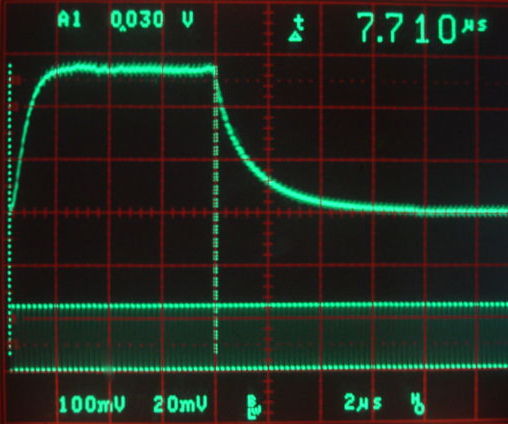
We pull the silicone off our epoxy-sealed head fixture. We cut back the lamp leads on D7.7 and attach another set of pins. We add a collar to each lead, connect the pins to the head fixture, and encapsulate in dental cement. Once the cement is hardened, we break the cement out of its red plastic cup. We immerse in hot water, see here. We pull on the lamp leads 100 times. Lamp artifact with 100% brightness is a few hundred microvolts, and consistent with no conduction between the lamp leads and the EEG leads. We put the ISL with head fixture, and the two-wire apparatus, in saltwater for the weekend.

UPDATE: [22-DEC-15] After four days in saltwater, we see 100-mV artifact when flashing the head fixture. The resistance between each wire and the surrounding water is around 5 MΩ. The resistance between the blue wire and the water is >40 MΩ, but between the red wire and the water is only 10 MΩ. We use Loctite Super-Glue Gel to glue single 3-mm long collars on two blue wires, and triple 1-mm long collars on two red wires.


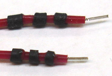
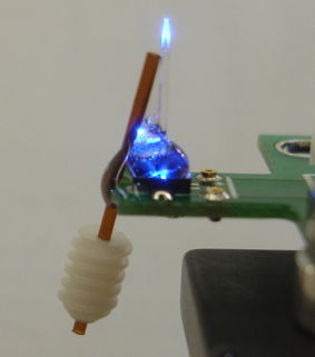
Figure: Triple Collars. Each collar is glued to the silicone with super-glue gel. Modelled after the triple o-ring seals we see in pacemaker connections.

Once the gel has cured, we can no longer slide the collars along the silicone. We embed the collars and wire tips in dental cement. When cured, we immerse in saltwater and arrange the free ends of the wires so we can measure easily the resistance between each wire and the water. We stretch all four leads by 15% one hundred times each while they are wet with saltwater. This stretching is within the elastic limit of the springs. We leave them for one hour. We combine a 10-V power supply with our 10-MΩ millivoltmeter to make an instrument capable of measuring resistance up to 100 GΩ. The water connection resistance is 20 GΩ for the two triple-collar red wires and >100 GΩ for the single-collar blue wires.

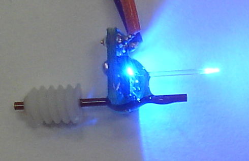
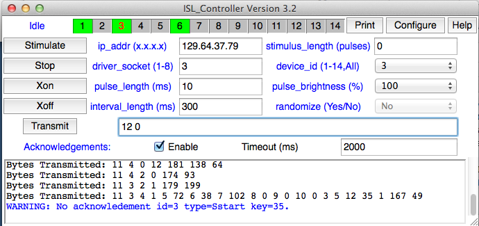
UPDATE: [24-DEC-15] Water connection resistances today are 100 GΩ, >100 GΩ, >100 GΩ, and >100 GΩ for red left, red right, blue left, and blue right. We connect the two red wires to D7.7's lamp power, with a blue LED in parallel. The blue LED flashes. We lower the ISL into a beaker of water with the cement fixture. We see 500 μV artifact. We do the same with the two blue wires, but connect no LED. We obtain 500 μV artifact. We pull 100 times on each of the two blue leads, stretching them by 30% each time while they are wet with saltwater. This stretching is at the elastic limit of the springs. We put the cement fixtures back in the saltwater with the ISL and observe the full-scale artifact below.


Figure: Artifact After Breaking Single-Collar Seals with 5-N Tugging. This display is centered with 65536 range, when it should be simply displayed with the same range. In simple display we see the entire waveform, in this display we are missing the tops of the artifact.

We have broken the seal. We do the same with the pair of triple-collar red wires, applying a force sufficient to stretch them by 30%, tugging 100 times. When we are done, the wires curl up because we have deformed the springs. We put the fixture back in the water and observe the same full-scale artifact. We smash open the cement fixtures. The collars are held firmly in the cement. But the wires now slide freely through the collars. The super-glue seal is broken. The leads are narrower because they have been elongated. They are no longer in compression where they pass through the collar.

The triple-collar performed no better than the single-collar. Once the super-glue seal breaks, the seal cannot recover. We would rather make a seal by compressing the silicone so forcefully that the lead cannot slide through the collar, even if we pull on it with sufficient force to stretch it by 30%. We have ordered narrower tubing and will try it when it arrives.

In the meantime, we are curious about the resistance of the shrink tubing and super-glue seal to saltwater. We assemble two single-collar seals. We measure their water contact resistance to be >100 GΩ. We put them in saltwater and set them in our oven to poach at 60°C.

UPDATE: [30-DEC-15] The two leads we left in saltwater at 60°C still provide isolation >100 GΩ. On day four of the six-day poach, we took the leads out and pulled on them one hundred times, stretching them by 15% each time. Isolation remains >100 GΩ.

UPDATE: [05-JAN-15] We have heat shrink tubing SFTW-203 in 1/16" size. Outer diameter is 2.0 mm before heating, 1.5 mm after. Inner diameter 1.5 mm before heating, 0.50 mm after. A 10.8-mm length is 10.1 mm after heating. We take a 100-mm long, 1-mm diameter silicone-insulated helical steel lead. We cut a 3-mm length of tubing and slide it onto the lead. We stretch the lead by 20 mm so its diameter reduces to around 0.8 mm, but the spring does not deform. We shrink the tubing and allow it to cool for ten seconds. We can slide the collar along the wire easily if when the wire is stretched by 20%, but the collar grips the wire when we relax the spring. We hold the 3-mm tube in one hand and the far end of the lead in the other. We pull on the collar. When the lead has stretched by 17%, the collar starts to move. We slide the collar back into place and repeat several times, obtaining similar results. We try a 10-mm collar. The spring extends by 28% before the collar slips.

We glue a 3-mm collar to the silicone lead with 3M's Vetbond. The glue does not appear to bond the silicone to the collar. We try Loctite Ultragel, allowing ten minutes to cure. We pull on the collar until the lead has extended by 33%, by which point the lead has deformed. The collar is still fixed in place. We try MED10-6607 dispersion as an adhesive. We wait one hour for it to cure and find that the collar appears to be lubricated by the silicone, which has not yet cured.

We apply 3-mm collars to two leads. We glue them in place with Ultragel. We have 3 mm of silicone insulation between the collar and the 2-mm exposed helix of steel. We encapsulate with dental cement. Keeping the cement fixture in water, we measure the resistance between the leads as we flex the leads 100 times, extending them by roughly 15% with each flex. Resistance is still >100 GΩ between each lead and the water.

CONCLUSION: It looks like a 3-mm length of the 1/16" SFTW-203 tubing with Loctite Ultragel glue provides a reliable seal against water penetration. We recommend that all four ISL leads be equipped with these collars.

Friday, December 11, 2015

Sealing the Lamp Leads

Following our discovery of conduction through tunnels, we perform the following experiment to test if we can, during implantation, seal the ends of the lamp leads with silicone. We make a head fixture with no guide cannula or fiber. We seal the LED with clear epoxy. We hold the fixture with the LED downwards and connect the leads of our D7.7 ISL, like this. We apply MED10-6607 silicone dispersion until it almost drips off the underside, see here. We allow the silicone to cure. After ten minutes it looks like this. After twenty, as below.


Figure: Silicone Around Lamp Leads, Twenty Minutes After Application.

We apply dental cement, allowing it to run off the underside. We start with thin cement, then thicken and make sure we cover the top side. The result is shown below. We note an obvious tunnel into the cement between the two lamp leads.


Figure: First Coat of Dental Cement over Head Fixture.

We allow the cement to cure for twenty minutes. We note that the pads around the LED are still exposed on the bottom side. We place the ISL and head fixture in water and observe full-scale lamp artifact. We surround the entire fixture with cement.


Figure: Encapsulating Coat of Dental Cement.

We let the above cement cure for ten minutes, then we place the ISL and head fixture in water. We get the following lamp artifact after one minute.


Figure: Lamp Noise Just After Dropping in Water.

We put hot water in the beaker. We take out the ISL and flex its lamp leads twenty or thirty times. We put the ISL and head fixture back in the water and let it settle down. We see the artifact below.


Figure: Lamp Noise 20 Minutes After Dropping in Water.

We move the EEG leads out of the water and record noise. We get this, which is pretty much the same as with the leads in the water. We wrap the lamp leads around in a loop with the EEG leads and put everything in the hot water. No change to the noise. We wait one hour to give capillary action time to move water into the dental cement.

Figure: Lamp Noise One Hour After Dropping in Hot Water. Range 800 μV, Interval 1 s, Pulses 50 ms, Pulse Period 500 ms. From top-left to bottom right: Lamp stimulus off, stimulus with 0% brightness, 20%, 40%, 60%, 80%, 100%, 100% with EEG leads out of water.

We see the artifact reversing direction as we increase the lamp current. If we re-arrange the leads, the artifact changes.


Figure: Lamp Noise for 100% Brightness After Rearranging Leads. Range 800 μV, Interval 1 s, Pulses 50 ms, Pulse Period 500 ms.

We now encapsulate the EEG leads with dental cement. When we immerse in water, the artifact remains much the same. It appears that our silicone sealing of the lamp leads has increased the resistance between the lamp power terminals and the water in the beaker.

UPDATE [14-DEC-15]: After 72 hours soaking in water, we flash the lamp power artifact has increased by at least a factor of ten, perhaps a hundred.


Figure: Lamp Noise 72 Hours After Dropping in Water.

UPDATE [15-DEC-15]: After a one-hour dry bake at 60°C, lamp noise for 100% brightness in water has dropped back to normal amplitude. We prepare another head fixture and cover all electrical pads on its top and bottom surfaces with clear DB270 epoxy, see below.


Figure: Epoxy Sealing of Head Fixture Conducting Surfaces.

We coated both sides, but stayed clear of the two sockets. We used a thin wire to apply epoxy between the sockets and the LED footprint. We cut the existing head fixture and cemented pins off D7.7 and solder new pins to the lamp leads. We strip and tin the EEG leads.

UPDATE [18-DEC-15] We connect lamp leads to the head fixture shown above and flash the light. We cover the pins and sockets with silicone. We wait twenty minutes, with the silicone curing above a bath of warm water. We touch the silicone with tweezers and note that it is not yet tack-free. If we were to apply dental cement, we would disturb and compormise the silicone coating. After one hour, it is tack-free. We lower the entire assembly and ISL and EEG leads into water and observe lamp full-scale lamp noise. We put the lamp in our mouth and cannot taste the signal, which means it must be less than 500 mV. So we suspect we are seeing lamp noise on the EEG of order 100 mV. We feel sharp edges around the corners of the circuit board. The silicone is discolored, because it has not had sufficient time to cure. We conclude that applying one coat of silicone during surgery is not sufficient to seal the lamp power electrodes.

Tuesday, November 17, 2015

Conduction Through Tunnels

In Electrical Coupling Through Dental Cement we showed that the resistivity of dental cement, wet or dry, was too great to cause the lamp stimulation artifact we observed on X for the first few weeks after implanting D7.2. A few weeks after implanting D7.6, the lamp stimulation artifact is a full-scale square wave, as shown below.


Figure: Lamp Pulse Artifact Two Weeks After Implantation. D7.6, 0% brightness, 10-ms pulses, 100 ms period. See M1447342849.ndf.

At ION on 12-NOV-15, we implant D7.5 and note the insulated exterior of the L+ and X+ leads are touching as we are about to apply dental cement. We believe the previous two implants were done exactly the same way. This time, we move the leads apart. If they were to touch, there would be a passage through the dental cement for water to creep along and so connect X+ to L+. Half an hour after implantation, we generate 0% brightness, 10-ms long pulses, with 100 ms period and see the artifact below on the X input.


Figure: Lamp Pulse Artifact Immediately After Implantation. D7.5, 0% brightness, 10-ms pulses, 100 ms period. See M1447350049.ndf.

We see a step up on X as the lamp power turns on and a relaxation afterwards. Brightness is 0%, so L+ is connected to +5V. When we turn off lamp power, L+ relaxes as a 10-μF capacitor discharges. At no time is Q1 turned on, so at no time is the LED draining the capacitor. With 100% brightness, the artifact on X is a pulse, as shown below. With 100% brightness, L+ drops quickly at the end of a pulse because the LED is connected to L+ for 200 ns after the end of the pulse, and conduction through the LED drains the 10-μF capacitor.


Figure: Lamp Pulse Artifact Immediately After Implantation. D7.5, 100% brightness, 10-ms pulses, 100 ms period. See M1447350049.ndf.

The artifact on X is consistent with a resistive connection between L+ and X+ of around 250 kΩ (the L+ lead carries +5V pulses, the X input's two skull electrodes have resistance is of order 1 kΩ, and the pulses on X are around 20 mV). We take two silicone-insulated steel leads and solder them to the pins of a connector. We cover the connector with dental cement, but leave the solder joints exposed. We tie the two leads in a knot to make sure they are touching. We put saltwater on the joints. We cover the leads, joints, and connector pins with cement. The resistance between the two leads is >40 MΩ (the largest resistance we can measure with our voltmeter). We allow the cement to cure. The resistance is >40 MΩ. We cover with salt water. Resistance is >40 MΩ. We wait half an hour, resistance has dropped to 120 kΩ. We pour away the saltwater and dry the cement surface. Resistance is 100 kΩ. Fifteen minutes later, resistance is 150 kΩ. We bake in the oven at 60°C for half an hour and measure 130 kΩ. One hour later, the resistance is >40 MΩ.


Figure: Conduction Through Tunnels. Visible through the pink cement are two leads we wrapped together to create a passage from one lead tip to another. The pink cement is at this moment covered by clear saltwater.

We know from long experience that water creeps along passages by capillary action. In this case, we have two solder joints being connected along a 20-mm tunnel by saltwater that has crept along the tunnel walls. The resistance of this saltwater connection is 100 kΩ. When implanted, every lead emerges from the head fixture somewhere. Where it emerges, there will be body fluids. And every lead creates a tunnel along which these body fluids can creep to the exposed conductor at the end of the lead. We suggest that these water films are the source of our lamp stimulation artifact.

Tuesday, September 22, 2015

Electrical Coupling Through Dental Cement

We have A3030D number D7.2 implanted at ION since 17-AUG-15. The day after implantation we observe full-scale artifacts on the EEG when transmitting commands, and the following 15-mVpp pulses when flashing the lamp.


Figure: Lamp Flashing Artifact for First A3030D Implanted, D7.2. Archive M1439901477.ndf, 2352 s.

Last week we observed only the 200-μVpp artifact we expect from our tests at OSI. We consider the possibility that dental cement (acrylic and powder) mixed with water is conducting until the water evaporates. We mix up dental cement with and without adding a few drops of water. When we add water, we get drops of water coalescing outside the cement. (Methyl methacrylate is hydrophobic.) Resistance between two probes placed 0.5 mm apart is greater than 10 MΩ in all cases. We cement two wires 5 mm apart and plug the electrodes of a 10-MΩ amplifier into the cement near each wire, but not in contact with the wire.


Figure: Cement Noise Coupling Measurement. We use an A3028E with 10-MΩ input impedance to pick up a 5-V square wave applied to two wires embedded in the cement.

We bake our apparatus at 60°C to make sure it is dry. We apply a 5-V, 10-Hz square wave to the two wires and observe the following on the A3028E output.


Figure: Cement Voltage Coupling. We have 10-MΩ input impedance and a 5-V, 10-Hz square wave applied to the wires.

We cover both amplifier electrodes with a few drops of water. The impedance between the elecrodes is now 600 kΩ measured at 0 Hz. The coupled signal drops to less than 100 μVpp from 10 mVpp. We dry off, apply a 5-Vpp sinusoid, and obtain the following graph of coupled amplitude versus frequency. The slope of the graph suggests the coupling through the cement is capacitive.


Figure: Cement Voltage Coupling versus Frequency. The initial positive slope shows coupling increasing as f. After 160 Hz, the attenuition of the three-pole low-pass filter changes the response to 1/f2.

At 100 Hz, we get 0.1% of the applied sine wave at our amplifier input, which suggests that our 10-MΩ input impedance is 0.1% of the impedance of the coupling capacitance, so that this capacitance is of order 0.2 pF. The dielectric constant of this cement should be around 4, so 0.2 pF can be made with two 2-mm square plates separated by 1 mm. We cut the blue X− lead. The coupled noise remains the same. We cut the X+ lead. The noise drops from 10 mVpp to 100 μVpp.

Our cement does not conduct electricity, even when we add water during mixing. The input impedance of the A3030D amplifier is 100 kΩ. If both electrodes are connected to the brain, the impedance between them will be closer to 1 kΩ. In either case, the noise coupled from a 5-V square wave applied to the same lump of dental cement will be less than 100 μV. Even if we disconnect the X− and leave X attached, artifact will be less than 100 μV.

Conduction through dry or wet cement cannot explain the artifact we observed from D7.2 when it was first implanted. Capacitive coupling cannot explain the artifact either, becasue the A3030D has input impedance only 100 KΩ.

Thursday, July 16, 2015

ISL Stage 7 Delivery

We ship to ION the devices shown below. There are ten Implantable Sensors with Lamp (A3030D) and fifteen Head Fixtures (A3024HF) of various types.


Figure: Batch ISL7 Deliverables. For a close-up of the A3030D see here.

Each ISL provides a 50-mm 915-MHz command antenna and a separate 30-mm 915-MHz data and acknowledgement antenna. The A3030D introduces support for longer interval lengths as well as random pulse generation. We need Version 4 of the ISL Controller Tool to command the A3030D. The new controller tool provides a version menu button to select between the A3030C and the A3030D. In other respects, the use and operation of the A3030D is identical to that of the A3030C we delivered in .


Figure: Output Power, Color, and Cannula Type for ISL7 Head Fixtures. We measure optical power with a photodiode and 40 mA LED current. All head fixtures are A3024HFC, except 7.1, which is A3024HFD.

The photograph below shows an example of the ISL7 head fixture with inclined silica cannula guide and cannula dummy installed.


Figure: Silica Guide Cannulas.

We ran out of cannula dummies and then silica guide cannulas during production of our fifteen head fixtures. Some we are shipping without cannula dummies. We run out of silica cannula guides and have no time to wait for more, so we use 10-mm steel cannula guides instead.


Figure: Steel Guide Cannulas.

We have been using silica guides because we believed they would transport less electrical noise into the brain. But our study of the sources of lamp activation noise suggests that a steel guide will cause no increase in lamp activation noise at the tip of the fiber. The guide will, however, affect the flow of the EEG signal in its neighborhood. We would like to learn from these three steel guides whether the silica guide is necessary or redundant.

We made twelve A3030Ds and all twelve are fully functional after encapsulation. The figure below shows all of them turning on at once in response to a multi-device XON command from our Command Transmitter.


Figure: Twelve A3030Ds Turning on Simultaneously.

We forgot to bind the X and L leads into pairs before we soldered them to our circuit boards. We bound the leads afterward encapsulation, which produced an unattractive finish on the previously smooth and rounded silicone-coated springs, as shown below.


Figure: Imperfect Silicone Binding in X and L Lead Pairs.

We believe there will be no problem implanting these lead pairs, not any compromise of their fatigue resistance due to the cosmetic problems with the finish.

Friday, July 10, 2015

Lamp Power Control

The Implantable Sensor with Lamp (A3030D) provides 0-100% control of the lamp power in steps of 20% by means of modulation of the lamp current, as we describe elsewhere. The 1-MHz modulation frequency is so high as to have no effect upon the activity of neurons nor our EEG amplifier. We connected an EZ500C470 470-nm blue LED to the lamp leads of an A3030D. At 100% power, the LED current is 35 mA. We varied the output power from 1-100% and measured battery current and optical output power of the LED at each step.


Figure: Optical Output Power and Battery Current versus Lamp Modulation Duty Cycle. Switching transistor is the NTR4003N. Compare to this measurement of modulation current in ISL5/6, which used the NDS355AN switching transistor.

The average ISL7 head fixture couples 44% of the LED light to the tip of its fiber. At 100% power, the LED produces 30 mW and we expect 13 mW at the fiber tip. The battery current and light intensity scale almost linearly with power setting. If anything, the 40% power setting is slightly more efficient in its conversion of battery energy into light energy than the 100% setting.

Prompt Acknowledgment

The Implantable Sensor with Lamp (A3030C) for ISL6 provided acknowledgment messages in response to acknowledgement request instructions from the Command Transmitter (A3029B). The transmission of these acknowledgements was, however, delayed by up to 2 ms after the A3030C processed the acknowledgment request. This meant that the best synchronization we could obtain between lamp pulses and the recorded X signal would be ±1 ms. One of our objectives for ISL7 is to improve the precision of the lamp and recording synchronization.

The Implantable Sensor with Lamp (A3030D) for ISL7 transmits an acknowledgment a fixed 60 μs after it processes a request. The ISL Controller V4 requests an acknowledgment immediately before it initiates a stimulus cycle, so the delay between the reception of the acknowledgment and the start of the first light pulse of the stimulus is deterministic. The figure below shows the delay for 100-Hz pulses.


Figure: Prompt Acknowledgment Timing with Respect to First Lamp Pulse. Top trace has a 60-μs pulse marking the moment the acknowledgement is transmitted. Bottom trace has a longer HI interval that marks the start of the first light pulse.

For a 10-ms interval (100-Hz pulses), the delay is 750 μs. When we increase the interval length to 100 ms (10-Hz pulses), the delay is 6.3 ms. The delay is a fixed 150 μs plus 2/33 of the interval length. The A3030D's prompt acknowledgments should allow us to synchronize stimulus and recording within a fraction of a millisecond.

ASIDE: While working on the prompt acknowledgments, we discovered that the A3030's radio-frequency oscillator, which is the same oscillator we use in our subcutaneous transmitters, needs roughly 50 μs to stabilize when it has been inactive for more than 100 ms. When transmitting at 512 SPS, the oscillator is never inactive for more than 2 ms. But in the ISL, we can request acknowledgment even when the data transmission is disabled, and in that case, the A3030C of ISL6 did not allow sufficient time for the oscillator to stabilize, so that acknowledgments were unreliable when data transmission was turned off. In the ISL7 we turn on the oscillator 60 μs before any acknowledgment transmission, and we get 100% reception of acknowledgments under all circumstances in a faraday enclosure.

Friday, July 3, 2015

Optogenetics Growth

The National Center for Biotechnology Information (NCBI) provides a database of published neuroscience papers. We used the database to obtain a count of the number of optogenetics papers published each year for the past ten years and obtained the figure below.


Figure: Number of Optogenetics Papers Published versus Year. The final point is a projection based upon the number published so far in 2015.

In the first seven months of 2015, 402 optogenetics papers have been published, as you can see for yourself with this search link. Assuming a constant rate of publication for the next five months, we project the total number in 2015 to be 689, and we added this point to the end of our graph.

Wednesday, June 24, 2015

Random Pulses

Firmware A3030D01.vhd for ISL7 (A3030D) is debugged and running. It provides random lamp pulses for any interval and pulse length. For a view of the modulation noise generated by random pulses, see our previous post. The ISL7 stimulus length is the expected number of pulses. The interval length is the average pulse period in milliseconds. The pulse length as a fixed multiple 30.5 μs.

The A3030D divides each pulse interval into thirty-two sections. For regular pulses, the A3030D always initiates a pulse in the first section and only in the first section. For random pulses, the A3030D initiates a pulse in each section with probability 1/32. Thus the average period of pulse initiation is the same as the interval length. With pulses longer than one section length, the pulses overlap. Pulses that occur at the end of an interval can overlap pulses occurring at the beginning of the next interval.

With 2-s intervals and 100-ms pulses, we counted 100 pulses in 207 s. With 100-ms interval and 10-ms pulses, we used a recording of lamp modulation noise to count 559 pulses in 60 s. The figure below shows the distribution of the number of pulses we counted per one-second recording interval.


Figure: Distribution of Pulses per Second for Random 10-ms Pulses with 100-ms Interval. Average pulse rate is 9.3 pulses/s. For 32-s view of recording and spectrum, see here.

We appear to have a passable approximation to a Poisson distribution of pulse generation. When the pulse length is significant compared to the interval length, the average number of pulses drops because the pulses are overlapping. But we still get 9.3 pulses/s average for 10-ms pulses at 10 Hz.

NOTE: The ISL6 accepted the interval length in multiples of 30.5 μs rather than 1 ms, so the ISL Controller Tool 4.1 has a version selector that allows it to control both ISL6 and ISL7 devices.

Quiet Modulation

The figure below shows lamp modulation noise on the X input of an ISL6 (A3030C) for 20% brightness. This noise occurs even with no lamp attached and no X input leads.


Figure: Lamp Modulation Noise on X for A3030C with 20% Brightness, 50-ms Pulses at 10 Hz.

When we modulate the lamp, we apply a 1-MHz clock signal to the gate of Q1 so as to turn on and off the lamp current. During lamp modulation, the A3030C battery current increases by around 5 mA. We suspect that this 5 mA causes the 3V0 output of our TPS70930 to drop by 500 μV, which in turn causes X to step up by 2 mV.

In the A3030C, Q1 is the NDS355AN, with 200 pF gate capacitance. We load our A3030D with NTR4003N for Q1. The figure below shows A3030D modulation noise for random 10-ms pulses.


Figure: Lamp Modulation Noise on X for A3030D with 80% Brightness, 10-ms Random Pulses at 10 Hz. Vertical range is 140 μV.

The new transistor reduces modulation noise to 50 μVpp. The NTR4003N has resistance 1.5 Ω, which is much larger than the 0.2Ω of the NDS355AN, but still insignificant compared to our 60-Ω lamp lead resistance.

Monday, June 22, 2015

ISL7 Head Fixture

The photograph below shows our first ISL Head Fixture (A3024HFD-B). Version D of the head fixture has the guide cannula cemented parallel to the optical fiber.


Figure: ISL7 Head Fixture with Blue LED (A3024HFD-B).

This guide cannula may be used to hold the head fixture in place during implantation. Once the head fixture is covered by cement, the silica guide cannula tube may be crushed with scissors, or a thin pair of cutters, just below the thread. We now have a more compact head fixture, with no guide cannula thread protruding from it, and the hole in the animal's skull must accommodate only the optical fiber. With our previous head fixtures, the skull hole had to accommodate both the fiber and the guide cannula.

In the above example we have roughly 3 mm space between the circuit board and the guide cannula thread. We believe this is sufficient to allow cement over the circuit board and still have space enough to cut the guide tube. But we await comments from ION before deciding the final geometry.

UPDATE [24-JUN-15]: ION tells us they would rather have the older A3024HFC-B.

Tuesday, May 12, 2015

Command Reception in Water

We put a self-propelled ball in a latex glove and attach ISL A3030C No6.1 to the outside. We place the combination in a tub of water and let the ball propel the ISL around the tub, immersed in water most of the time. We place the tub in an FE2A faraday enclosure.


Figure: ISL A3030C No6.1 Moving in Water.

We have only one BNC feedthrough in this enclosure. We use this feedthrough for the data reception antenna, which we connect to one input of an Octal Data Receiver. We must open a hole in the enclosure wall to allow the command antenna cable to enter. This compromises the isolation of our enclosure. We add two more antennas by raising the lid a little, but this does not help much. The result is 92% reception of data messages transmitted by the ISL.

We use the ISL Controller Tool to request acknowledgments from the ISL in response to commands transmitted by our 915-MHz Command Transmitter (A3029B). Each acknowledgement is a single 915-MHz message transmitted by the ISL and received with 92% probability by the Data Receiver. We request 116 acknowledgements and receive 100. These observations suggest the reception of 915-MHz commands by the ISL's crystal radio while swimming in water is roughly 94%.

Friday, May 8, 2015

ISL Stage 6 Delivery

We ship to ION the devices shown below. There are five Implantable Sensors with Lamp (A3030C), five Head Fixtures (A3024HFC-B), a 915-MHz Command Transmitter (A3029B), a Loop Antenna (A3015C) for command transmission, and various cables and connectors.


Figure: Batch ISL6 Deliverables. The five encapsulated A3030Cs are on the center right. For a close-up see here. The ISLs are encapsulated in black epoxy and clear silicone. On the left we have antenna cable, LWDAQ cable, and boost power supply for the command transmitter, which is itself the square metal box. We have three BNC feedthroughs to enhance an existing faraday enclosure. Five head fixtures are arranged in petri dishes below.

Each ISL provides a 50-mm 915-MHz command antenna and a separate 50-mm 915-MHz data and acknowledgement antenna. Command reception by a moving ISL in a faraday enclosure at 915 MHz is >95%, compared to less than 10% with our previous 146-MHz command frequency. We will perform more exhaustive tests of reception at 915 MHz in the near future. The A3030C can respond to commands with an acknowledgement on the 915 MHz auxiliary data channel, without disturbing or requiring simultaneous data transmission. Version 3 of the ISL Controller Tool allows us to detect acknowledgements collected by the Recorder Instrument.


Figure: ISL Controller Tool, Version 3. To receive acknowledgements from ISLs, the Recorder Instrument must be acquiring messages, either with the Loop command in the instrument itself, or the Record command in the Neuroarchvier.

The lamp leads are orange (L+) and purple (L−). They are held together with silicone so as to reduce the magnetic field they generate when the lamp current turns on. The EEG leads are red (X+) and blue (X−). These are held together with silicone so as to reduce the magnetic field they enclose when the lamp current turns on. The input impedance of the A3030C amplifier is only 100 kΩ, compared to 10 MΩ in previous devices. These precautions together reduce the amplitude of the spikes induced by lamp current.


Figure: Lamp Current and Voltage Noise on X for A3030C with Lamp Pins Above Water, White LED Attached, and Lamp and EEG Leads Running Close Together. Pulses of 100 ms every 200 ms.

With the A3030B, the above arrangement of the ISL in water produced voltage spikes much larger than the 20-mV range of the EEG amplifier. The noise spikes are now of order 200 μV. We appear to have reduced the induced noise amplitude by a factor of one hundred. We see a square wave much larger than 20 mV if we immerse the lamp power pins in the same water as the EEG pick-up leads. During implantation, we must make sure that there is electrical isolation between the lamp pins and the rat's body. The pins should be entirely covered with insulating cement.

Outside the light pulses, there should be no noise induced upon the EEG input because the A3030C turns off its boost regulator between pulses. During the light pulses, after the initial spike when the lamp turns on, we see the same 8 μV amplifier-generated noise we see outside the pulses. Because of the way it manages its power consumption when idle, the boost regulator generates less noise when it is delivering a continuous current than it does when it is delivering no current at all. Thus we see noise spikes only at the start and finish of each light pulse.

One feature does remain in the EEG recording during and after pulses: a relaxation in response to the step-component of the lamp current noise, rather than its pulse component. We cover the LED so its light does not land on the water near our EEG electrodes, and the step-component of the lamp current noise remains unchanged. It is not a photovoltaic effect. When the lamp power turns on, the lamp current leads now carry +5V and 0V instead of both carrying 0V. Despite the insulation around the lamp leads, this change affects the potential of the ISL body, and so induces a step change in the EEG amplifier input of order 50 μV, which then relaxes in response to the amplifier's high-pass filters. With shorter pulses, such as those shown on the same scale below, the steps cannot be seen.


Figure: Lamp Current and Voltage Noise on X for A3030C with Lamp Pins Above Water, White LED Attached, and Lamp and EEG Leads Running Close Together. Pulses of 10 ms every 100 ms.

The A3024HFC-B head fixtures are all equipped with blue LEDs. We measure power at the tip of the fiber to be 13-16 mW at 40-mA forward current. The average is 14.5 mW. The forward voltage drop of the LEDs is 2.8 V, we have 5-V lamp power, and the lamp leads have resistance 60 Ω. When implanted, the current will be 36 mA, so we expect power at the tip to be 13 mW. This power is sufficient to provoke optogenetic response with 5-ms flashes at 10 Hz.

When the lamp is on, the A3030C draws roughly 60 mA from its 190 mA-hr battery. Stimulating with 5-ms flashes at 10 Hz, the battery can run for 76 hours. With the internal state machines running, but no data transmission or lamp stimulation, the A3030C consumes only 60 μA. Allowing for one hour of stimulation per day, it should be possible to run a 60-day experiment with the A3030C.

The goals of ISL6 were to provide reliable command reception inside our 915-MHz enclosures, and to reduce the lamp-current noise induced in the EEG input. We look forward to seeing how well the devices perform when implanted.

Thursday, March 26, 2015

915 MHz Command Reception

We test the reception of ISL commands with our new 915 MHz Command Frequency. Our Command Transmitter (A3029B) is equipped with a 915.000 MHz 915 MHz Oscillator. This auxiliary circuit can stand alone, as shown below, or be soldered onto the A3030B circuit board as its source of 915 MHz.


Figure: The 915 MHz Crystal Oscillator (A3029XO-915). The circuit consists of a 457.5 MHz crystal oscillator, a frequency doubler, and an amplifier.

The Implantable Sensor with Lamp (A3030C) is equipped with a 50-mm data transmit antenna and a 50-mm command reception antenna. Both antennas are designed for 915 MHz when implanted in an animal, but as with SCT antennas, they work well enough in air as well. Now that we have the same frequency in use for data and command communication, the command antenna picks up the outgoing 915 MHz power from the transmit antenna, resulting in self-reception by the 915-MHz crystal radio, as shown below.


Figure: Self-Reception at 915 MHz. The 50-mm data and command antennas are parallel and separated by 2 mm. Top trace is the crystal radio output recorded with ×1 probe, 20 mV/div. Bottom trace is the 5-MHz data transmission clock recorded with ×10 probe, 1 V/div. Time is 2 μs/div. The data transmission lasts for 7.7 μs.

A self-reception pulse like this during command reception is likely to corrupt the incoming command. So the A3030C disables its data transmission during command reception and processing. Because commands begin with a minimum 5-ms pulse of 915-MHz power, the self-reception cannot be confused for command initiation, and once initiation has taken place, the self-reception is suppressed until the command is complete. Given that the 915-MHz command transmission will in any case overwhelm the much weaker data transmission, the suppression of data transmission during command transmission does not cause any additional loss of data.

We place a Loop Antenna (A3015C) at the center of a Faraday Enclosure (FE2B). We connect a white LED to our A3030C. We transmit a command to flash the LED once, and repeat this command at around 20 Hz. We move the A3030C around in the enclosure for 60 seconds and observe a total of 2 s of loss broken up into around six different intervals. We appear to have 97% reception of commands within the enclosure.

We work for several hours with the circuit, stimulating it, turning on and off the data transmission, and measuring the noise induced in the EEG amplifier by the lamp current pulses. We find reception within the faraday enclosure to be reliable. With the enclosure lid off, we can receive commands within roughly 100 cm of the command transmit antenna.

We have taken the well-establisehd SCT antennas and faraday enclosure and used them in reverse for ISL command reception. The A3015C loop antenna now transmits 1 W of 915-MHz power, and the 50-mm ISL command antenna receives this power. Meanwhile, the 50-mm ISL data antenna transmits 200 μW of 915-MHz power, and another A3015C loop antenna receives this power.

In the long run, we will be able to combine the two ISL antennas into one, and combine the two A3015C antennas into one, with the help of radio-frequency switches. The ISL can transmit "command received" messages through its data antenna, which means it will eventually be possible for us to know when a command has not been received. Just as we have multiple data reception antennas in the SCT system, we could have multiple command transmission antennas in the ISL system. If a command is not received from one command antenna, we can re-broadcast the same command with another command antenna.

Because the SCT 915-MHz communication works well for implanted SCTs, and because we can provide multiple command transmit antennas in the future, we believe we can rely upon 915-MHz command reception in implanted ISLs.

Friday, February 27, 2015

ISL Operating Range at 146 MHz

We compare reception of repeated commands by the A3024A and the A3030A. We fasten an example of each to a piece of cardboard.


Figure: Two ISLs Strapped to Cardboard for Command Reception Test.

The A3024A simply turns on its lamp when it detects radio-frequency (RF) power above a threshold. We set the threshold as low as we can. The A3030A turns the incoming RF signal into a sequence of byte instructions with a checksum at the end. When we send repeated commands to flash the A3030A lamp, the A3024A lamp illuminates while the command is being transmitted, and the A3030A lamp illuminates afterwards, provided the command has been received without corruption.

We use our 146 MHz Command Transmitter (A3029A) with boost power to produce the RF commands. We measure maximum range of reception, for a favorable orientation, and maximum range for reception in 95% of orientations. We also test reception with the two devices in water, as shown below.


Figure: Two ISLs In Water for Command Reception Test.

We measure maximum range for reception in water. Now we add 5 g of salt to the 500 ml of water and stir until dissolved. We measure maximum range again. We present our observations below.

TestA3030A No1.2A3024A No7
Robust Reception Range on Cardboard70 cm100 cm
Maximum Range on Cardboard250 cm600 cm
Maximum Range Held By Lamp and Dangling300 cm900 cm
Maximum Range in Water70 cm450 cm
Maximum Range in Saltwater70 cm450 cm
Table: Comparison of Reception for Encapsulated A3024A and Encapsulated A3030A.

It occurs to us that encapsulation or an exhausted battery might affect No1.2's reception, so we try an un-encapsulated A3030B with a fully-charged battery and measure maximum range in air. We get 250 cm, the same as for No1.2. We walk around with the lamp held in our fingers, and the device dangling below, and repeat our measurement of maximum range.

The A3030A must monitor and interpret the exact timing and content of the digital RF signal it receives on its two-turn loop antenna. Compared to the A3024A, which simply turns on its light in response to any received RF power, the A3030A has substantially shorter operating range (70% far in air for robust reception). In air, the A3030A's maximum operating range is one third that of the A3024A, but in water it is only one sixth that of the A3024A. In 1% saltwater, operating range is unchanged.

We place the A3030A in a jar of fresh water. It rests on the floor. We move it around 50 cm from the antenna and obtain robust reception. But there are orientations that are hard for us to obtain with the transmitter loose in the water, so we suspect that robust reception in all orientations would be closer to 30 cm. At ION, we observe robust operating range for an implanted device is only 20 cm.