Monday, March 25, 2013

Cladded Rod

We receive from Tim Beeman of Fiberoptics Technology Inc. a sample of 1.2-mm diameter clad rod. The core of the rod is made of Schott glass type F2, with refractive index 1.63 for blue light and 1.61 for red. The cladding is Schott 8250 glass with index 1.49. We expect the numerical aperture of the rod to be 0.66 for blue light and 0.61 for red.

We cut a 200-mm length and cover it with black epoxy of refractive index 1.5 for half of its length. We polish both ends with diamond grit paper to give an optical finish. The epoxy makes sure no light gets into the rod through its curved surfaces. It mimics the epoxy we have been using to bind our fiber to our LED, and makes sure that the cladding of the rod is what causes total internal reflection in the core, rather than the cladding-air interface. We set up the cladded rod as shown below, with a 650-nm red laser beam shining into one end, and a screen to observe the pattern of light emitted by the far end. We place a black foam baffle around the near end of the rod.


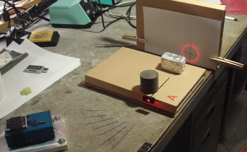
The light entering the rod emerges in a cone, making a ring on our screen. When a light ray enters a cylindrical rod at an angle θ to the axis, reflections off the rod surface re-direct the ray, but do not change the angle it makes with the axis. When the ray emerges from the rod, after many reflections of a perfectly-cylindrical rod, it emerges at an angle θ to the axis. We see two cones for small angles of incidence, but in the photograph we are at 40° and the ring is clear and sharp. With a photodiode and our graduated screen, we measure the power emerging from the end of the rod and the angle of the cone it emits. We obtain the following graphs.


Our measurement of transmission becomes unreliable for angles bigger than 60° because the rod end presents such a small area to the laser beam. Nevertheless, we see that the rod captures and transports more than 50% of the light incident upon one end for angles 60° and lower. With numerical aperture 0.61, we expect to get total internal reflection within the rod for angles less than 38°. We see 80% transmission at 40° and 25% at 60°. We believe these results are consistent with numerical aperture 0.61.

If we could obtain such a rod with diameter 400 μm, its numerical aperture for blue light would be 0.66. With such a fiber we could capture 43% of light emitted by our LED and transport it to the fiber tip. If we coat this rod with a layer of adhesive with index 1.32, the coated rod will have numerical aperture 0.96. It will capture and transport almost all the light that enters its base from our LED.

UPDATE: [27-MAR-13] Fiberoptics Technology tells us they can make 400-μm clad rod of the same type studied here. We have ordered a batch to arrive in a few weeks. The company tells us that they believe they can make the same diameter clad rod out of glass with index 1.75. When combined with their cladding, a core of index 1.75 provides numerical aperture 0.92, with no need to use low refractive index adhesives.

UPDATE: [15-APR-13] We try out a Luxeon Z LED, the blue LXZ1-PB01 version. The LED emits roughly 29 mW for 30 mA forward current. The emitting surface of the LED is 1.2 mm square. We place our 1.2-mm diameter, 200-mm long clad rod over it and observe roughly 40% of the power emerging from the other end. The rod covers 80% of the emitting surface of the LED, so it appears that the rod is transporting 50% of the light that enters its base.

UPDATE: [16-APR-13] We receive several hundred meters of clad rod from Fiberoptics Technology. Its diameter is 390 μm. We can bend it with into a radius of 10 cm. We take a 20-cm length, polish both ends, and glue one end to our LXZ1-PB01 blue LED. We use UV-curing adhesive of refractive index 1.54. We coat most of the length of the rod in the same adhesive. We run 30 mA through the LED, so that it emits 29 mW. The rod covers 8.3% of the emitting area of the LED, so we expect 2.4 mW to enter the base of the rod. If the numerical aperture of the clad rod is 0.66, we expect 44% of the light to reach the other end, or 1.0 mW. We measure 1.4 mW at the other end. We press the rod tip against a piece of white paper so we can see the cone of light it emits. The angle at the base of the cone is roughly 74°, which suggests a numerical aperture of 0.60.

Wednesday, March 20, 2013

Fiber-Cladding Adhesive

When we make a Head Fixtures (A3024HF), there is a stage at which we have the 7-mm long, tapered fiber positioned above the bare LED, ready to be glued in place with clear epoxy. At this step, we can apply current to the LED if we like, and observe light leaking out of the base of the fiber and shining out of its tapered tip.

We applied 30 mA to a blue EZ290 LED and held a 10 mm × 10 mm photodiode 5 mm above fiber tip. We obtained a photocurrent of 1.2 mA, which corresponds to 6.0 mW of blue light. This seemed odd to us, so we repeated the measurement several times. This particular LED was emitting 18 mW at 30 mA, and our calculations based upon the fiber's numerical aperture suggested that no more than 3 mW should be emerging in total from the fiber tip.

We applied clear epoxy (E30CL) to the fiber base, with power still applied to the LED. The intensity of the light emitted by the tip of the taper decreased immediately, while that of the light emitted from the base of the fiber increased. We measured once again the power 5 mm from the tip of the fiber. We observed only 1.5 mW. Later, we measured power emitted in all directions with the same fiber tip and obtained a total of close to 3 mW.

The numerical aperture of an optical fiber is the greatest angle a ray entering a polished, perpendicular face can make with the fiber axis and still be constrained within the fiber by total internal reflection. This total internal reflection can occur at the core-cladding boundary, which is always available, or at the cladding-glue boundary, or the cladding-air boundary. The following calculation shows how the numerical aperture of the fiber is affected by glue and air.


The WF300/330/P37 fiber has a cladding of fused silica, with refractive index n3 = 1.458. Its specified numerical aperture is 0.37, which is the numerical aperture we get by total internal reflection at the core-cladding interface. The refractive index of the air outside the base of the fiber is n1 = 1.000. Using the equation derived above, we conclude that the germanium-doped core of the fiber has refractive index n2 = 1.504. Now suppose we surround the fiber with clear epoxy. Our clear epoxy has refractive index n4 = 1.5. Because the glue has higher refractive index than the cladding, there will be no internal reflection at the cladding-glue boundary.

When we are assembling a head fixture, we hold the fiber in a clamp that touches the cladding along three contact lines each 5 mm long, so the majority of the cladding surface is exposed to air. Under these conditions, our equation gives us a numerical aperture of 1.1, which we interpret to mean that any ray entering the fiber will be trapped by internal reflection at the cladding-air boundary. Thus we expect to see all the power entering the base of the fiber emerging at the tip. Our fibers were not perfectly clean, so we were losing some light because of oil on the cladding surface, but we do see four times as much power when we hold the fiber without glue in a clamp.

Suppose we use a glue with a lower refractive index than the cladding. We will now see total internal reflection at the cladding-glue interface. Consider the MY132, UV-curing adhesive, designed specifically for cladding optical fibers. It is expensive (roughly $300 for 10 ml). But its refractive index is only 1.324. With this adhesive fastening the fiber to our LED, and coating the fiber up to the base of the taper, the numerical aperture of the fiber would be increased to 0.71, which means that light within a ±46° cone will be accepted and constrained within the fiber.

With numerical aperture 0.37, we expect to capture 14% of the light emitted by an EZ500 LED. This calculation is borne out by our measurements. But with numerical aperture 0.71 we will capture 51% of the emitted light. The power delivered to our fiber tip will increase by almost a factor of four.

We have learned from Cree that their EZ290 LED will not produce the optical power we expected. The most efficient LED we can buy is the EZ500. We believe the most efficient class of these LEDs will emit 30 mW of blue light with forward current 30 mA. A well-positioned 400-μm diameter fiber covers 90% of the light-emitting surface of the EZ500. Thus we can hope for 27 mW to enter our adhesive-coated fiber, and 14 mW to emerge from the tip. We plan to order a reel of the most efficient class of EZ500 LEDs, and a sample of the MY131MC adhesive, and test our hypothesis.

Another way to increase the numerical aperture of the fiber is to increase the refractive index of its core. We have ordered a sample of 1.4-mm diameter borosilicate glass rod from Fiberoptix, which has refractive index 1.6. We will try to stretch this to create a fiber of diameter 400 μm which, when coated by MY132, will provide numerical aperture 0.90 and therefore capture 81% of the LED light. We would then be able to deliver 22 mW to the fiber tip.

Friday, March 15, 2013

Stage Three Delivery

Today we ship to ION the following components:

  • 5 of Head Fixture (A3024HF)
  • 1 of Implantable Lamp (A3024A)
  • 2 of White Test Lamps
  • 1 of Command Transmitter (A3023CT)
  • 1 of Booster Amplifier (ZHL-3A)
  • 1 of 24-V Power Supply for Booster Amplifier
  • 1 of Flexible Antenna with 2-dB Attenuator
  • 1 of Telescoping Antenna with BNC elbow
  • 1 of Coaxial Cable with 12-dB Attenuator

Early next week we plan to ship the following, which will complete the deliveries required by ISL Stage Three, Design and Construction of the Implantable Lamp.

  • 4 of Implantable Lamp (A3024A)

In the photograph below, we see the Command Transmitter (A3023CT) connected directly to the Flexible Antenna. The 2-dB attenuator at the base is necessary to stabilize the A3023CT's power amplifier. This arrangement supplies 100 mW of 146-MHz RF power to the antenna, and is easy to set up. We use this arrangement for test that do not require us to operate more than 50 cm from the antenna. We determine the length, number, and spacing of RF power pulses using the same control program that we use with the Lamp Controller (A2060L).


The same photograph shows one Implantable Lamp (A3024A) flashing a white LED, and another at with a paper insulator around its L+ lead. The paper insulation is needed to stop the A3024A contact pins from touching when stored in a bag. If they touch and the lamp is stimulated, we will waste battery capacity supplying current to the lead resistance. The white LED is one of our White Test Lamps, which we have equipped with sockets to accept the pins on the tips of the A3024A leads. The test lamp leads have color codes and socket orientation to mimic the head fixtures and the colors of the A3024A leads.


When we want to operate farther from the antenna, and allow for random movements of the receiver, we add a ZHL-3A booster amplifier between the A3023CT and the antenna, and we use a telescoping antenna instead of the shorter flexible antenna. The telescoping antenna is more efficient. In this arrangement, we must be sure to insert the 12-dB attenuator between the A3023CT and the ZHL-3A, so as to protect the ZHL-3A's input from over-drive. With this arrangement, we obtain 100% reliable stimulation of the implantable lamps at range 1 m in our basement laboratory and 2 m in a faraday tent. This operating range is double that which we set as our target.


The telescoping antenna, being 1 m tall, needs to be vertical or else it will fall over. The ZHL-3A amplifier gets warm after a few minutes. We have found it to be rugged, but the manufacturer recommends that you connect its load (the antenna) and input (the cable carrying 146 MHz) before you connect power (the 24 V supply) in order to protect it from over-drive.

The Head Fixtures (A3024HF) are equipped with sockets for the A3024A contact pins. They are equipped with dummy cannulas in their guide cannulas. We have applied black epoxy over the clear epoxy that holds the fiber to the LED and the circuit board to the guide cannula. The black epoxy serves to mask light that escapes through the base of the fiber, which is roughly 85% of the light emitted by the LED. By masking this light, we are better able to estimate the power emitted by the fiber tip, and we avoid flashing a bright light into the subject animal's field of view, which might otherwise corrupt our experiment. The disadvantage of our black covering of epoxy is that the experimenter may not be able to confirm by inspection whether or not the implantable lamp is responding to commands. In future designs, we will consider placing a separate LED on the back of the head fixture to emit a small amount of light as an indicator for the experimenter.


It is hard to measure the total power emitted in all directions by the fiber tapers. Nevertheless, we tried to do so and obtained 2.5±1 mW. When we tested the fibers before we tapered them, we obtained 3±0.2 mW. These results are consistent, and suggest that the total power is a little below 3 mW. This 3 mW is well below our target of 10 mW. In the future, we will increase the power output at the tip by using a higher numerical aperture fiber, or higher drive current, or a more efficient LED, or some combination of all three modifications.

Monday, March 4, 2013

Prototype Head Fixture

The following photograph shows our first assembled fiber and cannula Head Fixture, following the design we presented earlier. The small ruler graduations are 0.5-mm. The fiber diameter is 300 μm.


Part (4) is the fiber, one end of which is glued with clear optical epoxy to an EZ500 LED mounted on the circuit board. This fiber is a dummy we used to make a prototype head fixture. Its tip is sheared off at an angle instead of tapered with a flame.

Part (1) is the L+ lead from an Implantable Lamp (A3024A). Part (2) is the connector pin on the end of the L− lead from the same device. These pins plug into two sockets on the Head Fixture. Part (3) is the L− socket. The L+ socket is obscured by L−. Part (8) is the head fixture circuit board. Part (5) is a silica guide cannula. Part (6) is the threaded pedestal on the guide cannula. Part (7) is a smoothing capacitor to reduce noise induced in EEG recordings.