Tuesday, February 24, 2015

915-MHz Command Frequency

The reliable operating range of command transmission in ISL Stage 5 appears to be 3 m with the ISL held in open air, 50 cm with the ISL in a jar of water, and only 20 cm when implanted in a rat. Within one of our radio-frequency isolation chambers, command reception at 146 MHz is reliable only up to 20 cm, and in one of our Faraday enclosures, reception can be unreliable even at 10 cm. Meanwhile, data transmission at 915 MHz from implanted A3030Bs is reliable in isolation chambers and Faraday enclosures, but not reliable out in the open. Another problem with the 146 MHz command reception is the 30-mm diameter, two-turn loop antenna it requires on the implanted ISL device. This antenna is tolerated by rats, but would be intolerable to mice. A higher command frequency will mean a smaller antenna.

The Command Transmitter (A3030B) and ISL (A3030C) of ISL Stage 6 will use a command frequency of 915 MHz. We already have data transmission working well at 915 MHz. In theory, if we can transmit 915 MHz with our Loop Antenna (A3015C) and receive with our 50-mm bent wire antenna, we can do the same in reverse. We begin by adapting the crystal radio of the A3030B to operate at 915 MHz. The traces below show the tuning we achieved with C7 = 0.5 pF, C8+C9 = 1.8 pF, and L1 = 2.7 nH (see schematic).


Figure: Crystal Diode Output (VR) vs. Frequency. The bottom trace is 5 mV/div obtained with a ×1 probe on VR. The top trace shows 890-930 MHz, with the zero-crossing at 910 MHz.

We apply 20 mW of 910 MHz to an A3015C antenna. We hold and rotate our A3030C at range 30 cm. We obtain ≥20 mV demodulated signal strength, which is sufficient for robust command reception. With 1000 mW of 910 MHz, assuming an inverse square law of power distribution, we expect to get robust reception at range 2 m in air.

We adapt the radio frequency amplifier of the A3029A to amplify a 915 MHz input and generate as much power as it can at its command antenna output connector. We arrive at the following amplifier circuit, in which the amplifier gives us 10 V peak-to-peak, which the matching network boosts to 24 V peak-to-peak. We end up with 800 mW available for our loop antenna. Our calculations suggest that this is the maximum possible power we can deliver in a stable manner with our chosen amplifier chip and our 5-V amplifier power supply.


Figure: Matching Networks Around 915 MHz Power Amplifier.

With these two outcomes, it appears that we will indeed be able to adapt the Stage 5 circuits to 915 MHz for Stage 6. The A3030B will have two 50-mm antennas: one for data transmission and one for command reception. These two antennas can be combined in a future design, but not by adapting our existing circuit. The A3029B will have its own precision 915-MHz oscillator to provide input to the power amplifier. We plan to load this oscillator onto the auxiliary connector footprint, thus leaving the metal enclosure intact.
Thursday, January 15, 2015

Lamp Current Noise

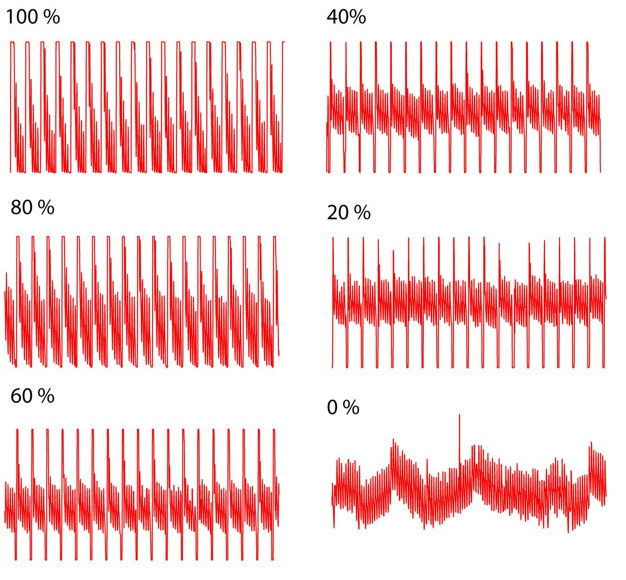
In November 2014, before we shipped the ISL5s, we put one in water with a head fixture and obverved up to 10 mV of switching noise on the EEG monitor when we flashed the lamp. The amplitude of the noise did not correlate well with proximity of the lamp and the EEG leads. After half an hour of work, we ran out of time to examine the problem. Since then, Rob Wykes has implanted No2.5 and observes the following noise on the EEG signal during what appears to be 18-Hz, 10-ms optical pulses of 0-100% power.


Figure: Lamp Flashing Noise on EEG Input. ISL No2.5 is implanted in a rat. One-second intervals, full 27-mV voltage range.

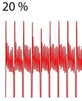
Detail of the 20% power noise, shown below, shows a rising and falling edge on the pulse start and stop, and another 130-Hz interference that we see also when the light power is 0%.


Figure: Lamp Flashing Noise on EEG Input for 20% Power, Detail. ISL No2.5 is implanted in a rat.

We believe both these types of noise are electrical and magnetic, rather than photovoltaic. The boost regulator runs even at 0% power, so its switching noise is most likely the source of the persistent 130-Hz. The large spikes when the lamp switches on and off may be due to proximity of the four leads, or be electrical through the body fluids. We do not see such noise when the devices are unencapsulated and in air.

Friday, November 14, 2014

ISL Stage 5 Delivery

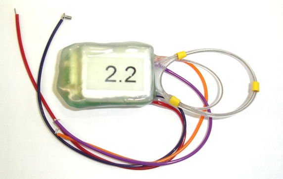
We ship to ION the devices shown below. There are five Implantable Sensors with Lamp (A3030B). These are encapsulated in acrylic, transparent epoxy, and clear silicone. They include command receiver, lamp power supply, EEG amplifier, and data transmitter.


Figure: ISL Stage 5 Deliverables. We have 5 Head Fixtures A3024HFC-B and 5 ISL A3030B. The ISL No2.1 is non-functioning. We see the two-turn command antenna bound up with the one-turn data antenna.

The lamp wires are 100-mm long. The orange lead is L+ and the purple lead is L−. Each pair of lamp wires presents resistance 65 Ω to the flow of lamp current, so that the current through a blue lamp will be close to 35 mA. The EEG leads are 150 mm long. The blue one is X+ and the red one is X−.


Figure: Implantable Sensor with Lamp, A3030B.

In addition to the five ISLs, we are sending five Head Fixtures (A3024HFC-B) with blue LEDs. These are No3.4, 3.5, 5.1, 5.2, and 5.2. They produce 13, 13, 13, 15, and 14 mW blue light respectively at their fiber tips when supplied with 40 mA forward current, as marked on their petri dishes. Our A3030B lamp current is 35 mA, so the light emitted by the fiber tips when connected to the A3030B will be around 12 mW.


Figure: ISL Controller Tool.

Accompanying these circuits, we have the ISL Controller Tool, Version 2.2, which fixes some device-addressing problems present in Version 2.1. Download the script and place it in the LWDAQ Tools/More folder to replace any previous version of the tool you may have installed.

Four of the five A3030Bs are fully-functional: No2.2-2.5. But No2.1 failed after water wash and encapsulation, along with our spare circuit, No2.6. In the future, we have to figure out how to load the battery and wash the solder joints to make the circuit clean, without damaging the lithium-ion battery, which is vulnerable to liquid water, and without causing the circuit, which has power attached, to enter a parasitic state that drains the battery quickly.

Before shipping, we used No2.2 to measure the effect of lamp flashing on the EEG amplifier. We will report on our observations in the next post.

Wednesday, October 1, 2014

EEG Monitor Incorporated

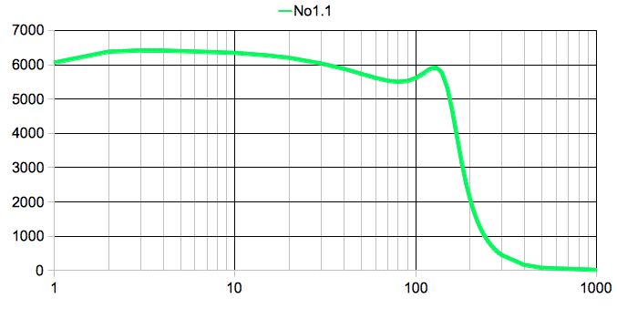
We have our first Implantable Sensor with Lamp (A3030B) with functioning EEG amplifier and transmitter. The circuit includes the same Command Receiver and Lamp Power Supply as the existing A3030A, but we have now loaded the amplifier, ADC, radio-frequency oscillator, transmit antenna, and electrode leads. In order to get the digitization and transmission working, we translated our existing data transmitter firmware from its original ABEL to the more modern VHDL required by the A3030B's CPLD. The graph below shows the frequency response of the amplifier as observed in the Recorder Instrument after digitization at 512 SPS, transmission at 902-928 MHz, and reception in by loop antenna in a faraday enclosure.


Figure: Amplitude versus Frequency for 11-mV pp input on X. We see the bump in gain at around 130 Hz, which is a characteristic of our three-pole Chebyshev low-pass filter.

We turn on and off the A3030B's 915-MHz radio-frequency data transmission with 146-MHz radio-frequency command transmissions. The A3030B is either digitizing and transmitting its analog input, or it is doing nothing with its analog input. We update the ISL Controller Tool to permit us to turn on and off data transmission with the press of a button.


Figure: The Updated ISL Controller Tool. We now have buttons Xon and Xoff to turn on and off data transmission. We have labels along the top that indicate the status of each of fourteen possible ISLs.

Of particular concern to us was interference between the data transmission and command reception. With data transmission turned on, there was the possibility of the 915-MHz power on the transmit antenna disrupting or stimulating the 146-MHz command receiver. But no disruption appears to occur. Command reception is equally effective with simultaneous data transmission.

We are also concerned about the effect of command transmission upon the A3030B's analog input. In an earlier experiment, we observed 20-mV pulses at the analog input in response to command transmission at range 70 cm. The A3030B includes a 40-kHz low-pass filter (R5, R6, and C here) at the analog input, which we expect to attenuate 146-MHz by a factor of 3500. In initial experiments, we are unable to observe any effect upon the analog input by command transmission. We will conduct more thorough measurements in the coming weeks. For now, with 100 μV of mains hum on our un-encapsulated circuit with external battery, we see no effect, so it appears that we have reduced its magnitude to less than 100 μV.

Only one A3030B exists today, which we made entirely by hand. We have ordered another thirty to be assembled by machine and shipped to us by the end of October. Of these, we will use 5, 5, and 10 to fulfill ISL Development Stages 5, 6, and 7 respectively.

Wednesday, September 17, 2014

ISL Stage 4C Delivery

We ship to ION the devices shown below. There are five Implantable Sensors with Lamp (A3030A). These are encapsulated in acrylic, clear epoxy, and clear silicone. They do not include EEG monitors, but they can be commanded individually, and instructed to perform extended optical stimuli with a single command. All five have 100-mm long stretched helical leads and through these they deliver 40 mA to an implantable lamp.


Figure: ISL Stage 4C Deliverables. We have (1) Rubber Duck antenna, (2) telescoping half-wave antenna, (3) Command Transmitter, (4) Head Fixtures A3024HDC-B, (5) Implantable Lamps Circuits A3030A.

There are five Head Fixtures (A3024HFC-B). All produce blue light. The power output from the taper tip at 40 mA forward current is written on the top of their petri dishes. Head fixture No3.1 produces 18 mW, which it obtains from a total lamp output of 34 mW. Its coupling efficiency is 53%, which is a little over our theoretical maximum, and 3.4 mW higher than our previous best head fixture. Another head fixture provides 15 mW. For more details see here.

The Command Transmitter (A3029A) is programmed to transmit serial commands to the ISLs. We plug LWDAQ power into its RJ-45 socket, and 24-V boost power into its power jack. We do not include a boost power supply in our ISL4C shipment. The boost power supply from the ISL4B shipment is still at ION, and will do the job. Note: we sometimes have to reset the LWDAQ Driver before the green power light illuminates on the A3030A.

We operate the Command Transmitter (A3029A) with our new ISL Controller tool, which you can download here. Place the TclTk text file in your LWDAQ Tools folder, or run it with the Run Tool option, and a window like the one shown below will pop up.


Figure: ISL Controller Tool in LWDAQ Software. The A3030A does not provide data transmission (Xon and Xoff).

The A3030A does not support randomized pulse generation. But it does support lamp dimming to 0%, 20%, 40%, 60%, 80%, and 100% of maximum intensity. The ISL Controller allows you to select the lamp intensity with a menu button. We can send the stimulus command to all A3030As or to an individual A3030A. We select channel 1-14 for individual devices, according to the serial number label on its battery.

We ship two antennas. One is a telescoping half-wave 146-MHz antenna. With this antenna we obtain reliable reception at ranges 0-1 m. The other is a short, flexible antenna (called a "rubber duck" antenna). With this one, we obtain reliable reception at ranges 0-50 cm.

We hope that ION's implantation of these devices will answer the following questions. Does the encapsulation resist condensation and corrosion? We have clear encapsulation to allow us to examine the devices after explantation. At what range is command reception reliable? What lamp power is required to provide stimulation, and what pulse length and frequency is optimal for stimulation?

We will visit ION on 16-OCT-14 to measure the operating range. In the meantime, we will start work on the A3030B, the same circuit as the A3030A, but with the EEG amplifier and data transmitter loaded.

Thursday, August 21, 2014

Corrosion of Lamp Circuit

Upon a visit to ION in July, we observed that lamp circuit No2.6 (with blue light) did not flash at all, and No2.1 (with green light) responds only with the antenna 10 cm from the animal. This was nine weeks after implantation. The head fixtures were still attached, the circuits were implanted, and the animals were healthy and active.

Now we have circuits No2.1 and No2.6 after removal from the animals, cleaning, and shipping to our office, and backing for 24 hours at 60°C. Circuit No2.6 does not respond to stimulus at all, but we poke through the encapsulation and measure 3.4 V on its battery, which is more than sufficient to power the circuit. Meanwhile, No2.1 responds well, with full operating range.

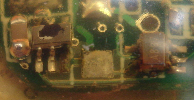
We encapsulated our A3024B-M and A3024B-R with clear, five-minute epoxy and then four coats of silicone. The silicone is about 1 mm thick all around. The epoxy coats the circuit and battery, making a better surface for the silicone to adhere to. We did not apply an acrylic coating to the circuit board, nor did we place the epoxy in a vacuum to remove cavities. There would have been little point in trying to remove cavities when the setting time of the epoxy was only a few minutes. After nine weeks implanted in large, healthy rats, the external silicone encapsulation of both devices is intact, and none of the leads show any sign of fatigue. But both circuits, within the unbroken encapsulation, are corroded. The photograph below shows corrosion on pins and pads carrying VBAT in No2.6.


Figure: Corrosion of Pins and Pads Carrying VBAT After Nine Weeks Implanted, A3024B-R No2.6. Click for higher resolution.

The battery voltage in the above circuit remains 3.4 V, but we cannot get lamp power out of the leads. The part on the left is U2, the boost regulator, and the part on the right is U1, the comparator. We see no trace of metal left in U2-6 or U1-5, the power supply pins for the two components. Meanwhile, circuit No2.1 now responds perfectly, with good operating range. But it, too, shows corrosion in the same location.


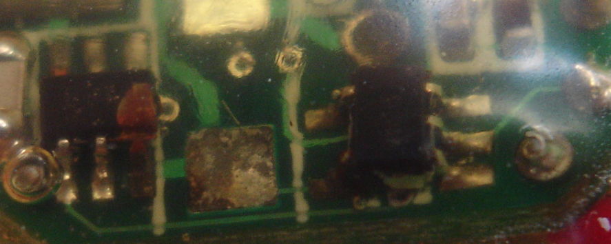
Figure: Corrosion of Pins and Pads Carrying VBAT After Nine Weeks Implanted, A3024B-R No2.1. Click for higher resolution.

In No2.1, we do see metal remaining in U2-6 and U1-5. The corrosion is a certain sign of condensation within the encapsulation, which we are familiar with from our subcutaneous transmitters. Condensation across R1, a 10-MΩ resistor, would reduce the resistance of R1, raising the device's power threshold, thus shortening its operating range.

UPDATE: [21-NOV-14] We encapsulated our Stage Four Implantable Lamps, of which No2.1 and No2.6 are two examples, in DP100 fast-curing epoxy. Its data sheet does not say that this epoxy corrodes copper, but other epoxies, such as DP270 state that they do not corrode copper, and so are recommended for encapsulation of electronic components.

Monday, August 11, 2014

ISL Prototype in Development

We are assembling and testing our prototype Implantable Sensor with Lamp (A3030). For details of development, see the manual. For circuit diagram, see S3030_1. The device combines an Implantable Lamp (A3024) with a single-channel Subcutaneous Transmitter (A3028B).


The A3030's logic chip contains enough programmable logic to implement a microprocessor, enough working memory to record several seconds of EEG, and enough non-volatile memory to retain its operating instructions. Our first implementation of the A3030 will provide only basic logic functions, such as decoding commands and generating trains of optical pulses. But in the long run, we plan to build a microprocessor in the logic chip. The A3030 provides a TQFP-100 footprint for the logic chip, which is 14 mm square. Future ISL devices will use the WLCSP-25, which is 2.5 mm square. Being a prototype circuit, we wanted to be able to make the A3030 by hand. The WLCSP-25 package is a 0.4-mm pitch BGA, which would be very difficult for us to load by hand.

The A3030's lamp power supply is almost identical to that of the A3024, except that it includes a switch to modulate the LED current at 5 MHz so as to dim the average power output without losing efficiency, and without producing any electromagnetic noise that would be picked up by our EEG monitor.

The command receiver uses the same split-capacitor tuning network as the A3024, except we now have a dual tuning diode to give us double the received signal amplitude. We hope this additional diode will increase the operating range of command transmission.

The EEG monitor is similar to the one in the A3028. It provides one channel with gain ×100 and cut-off at 160 Hz. To isolate the amplifier input radio-frequency noise and LED switching noise, we have a low-pass filter in front of the input, as we proposed earlier.

The A3030 has no magnetic sensor with which to turn on and off. We will switch it on and off with 146-MHz RF power through its Command Receiver. Each command transmission will activate, at least temporarily, all devices within range. After the command, some devices may remain awake, others may go to sleep, depending upon the commands transmitted. We will activate the EEG transmission through the Command Receiver also. The active current consumption of the A3030 with no EEG transmission and the lamp turned off is around 60 μA, which is much higher than the A3028's 20 μA and the A3024's 2 μA. This higher consumption is due to the higher-capacity logic chip.

The A3030 will be powered by a 382030 160 mA-hr lithium polymer battery. This battery is rechargeable, and we will be able to recharge it up until the time we encapsulate the entire device for implantation. After that, its value lies in its ability to delivery over 200 mA with minimal drop in output voltage.