The Command Transmitter (A3030B) and ISL (A3030C) of ISL Stage 6 will use a command frequency of 915 MHz. We already have data transmission working well at 915 MHz. In theory, if we can transmit 915 MHz with our Loop Antenna (A3015C) and receive with our 50-mm bent wire antenna, we can do the same in reverse. We begin by adapting the crystal radio of the A3030B to operate at 915 MHz. The traces below show the tuning we achieved with C7 = 0.5 pF, C8+C9 = 1.8 pF, and L1 = 2.7 nH (see schematic).

Figure: Crystal Diode Output (VR) vs. Frequency. The bottom trace is 5 mV/div obtained with a ×1 probe on VR. The top trace shows 890-930 MHz, with the zero-crossing at 910 MHz.
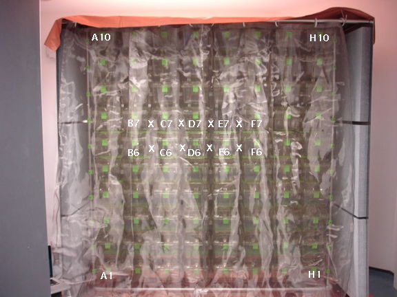
We apply 20 mW of 910 MHz to an A3015C antenna. We hold and rotate our A3030C at range 30 cm. We obtain ≥20 mV demodulated signal strength, which is sufficient for robust command reception. With 1000 mW of 910 MHz, assuming an inverse square law of power distribution, we expect to get robust reception at range 2 m in air.
We adapt the radio frequency amplifier of the A3029A to amplify a 915 MHz input and generate as much power as it can at its command antenna output connector. We arrive at the following amplifier circuit, in which the amplifier gives us 10 V peak-to-peak, which the matching network boosts to 24 V peak-to-peak. We end up with 800 mW available for our loop antenna. Our calculations suggest that this is the maximum possible power we can deliver in a stable manner with our chosen amplifier chip and our 5-V amplifier power supply.

Figure: Matching Networks Around 915 MHz Power Amplifier.
With these two outcomes, it appears that we will indeed be able to adapt the Stage 5 circuits to 915 MHz for Stage 6. The A3030B will have two 50-mm antennas: one for data transmission and one for command reception. These two antennas can be combined in a future design, but not by adapting our existing circuit. The A3029B will have its own precision 915-MHz oscillator to provide input to the power amplifier. We plan to load this oscillator onto the auxiliary connector footprint, thus leaving the metal enclosure intact.
No comments:
Post a Comment