Now we have circuits No2.1 and No2.6 after removal from the animals, cleaning, and shipping to our office, and backing for 24 hours at 60°C. Circuit No2.6 does not respond to stimulus at all, but we poke through the encapsulation and measure 3.4 V on its battery, which is more than sufficient to power the circuit. Meanwhile, No2.1 responds well, with full operating range.
We encapsulated our A3024B-M and A3024B-R with clear, five-minute epoxy and then four coats of silicone. The silicone is about 1 mm thick all around. The epoxy coats the circuit and battery, making a better surface for the silicone to adhere to. We did not apply an acrylic coating to the circuit board, nor did we place the epoxy in a vacuum to remove cavities. There would have been little point in trying to remove cavities when the setting time of the epoxy was only a few minutes. After nine weeks implanted in large, healthy rats, the external silicone encapsulation of both devices is intact, and none of the leads show any sign of fatigue. But both circuits, within the unbroken encapsulation, are corroded. The photograph below shows corrosion on pins and pads carrying VBAT in No2.6.

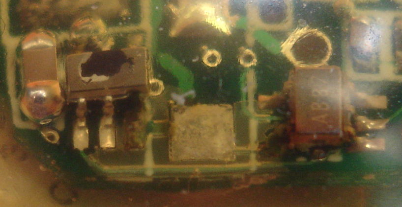
Figure: Corrosion of Pins and Pads Carrying VBAT After Nine Weeks Implanted, A3024B-R No2.6. Click for higher resolution.
The battery voltage in the above circuit remains 3.4 V, but we cannot get lamp power out of the leads. The part on the left is U2, the boost regulator, and the part on the right is U1, the comparator. We see no trace of metal left in U2-6 or U1-5, the power supply pins for the two components. Meanwhile, circuit No2.1 now responds perfectly, with good operating range. But it, too, shows corrosion in the same location.

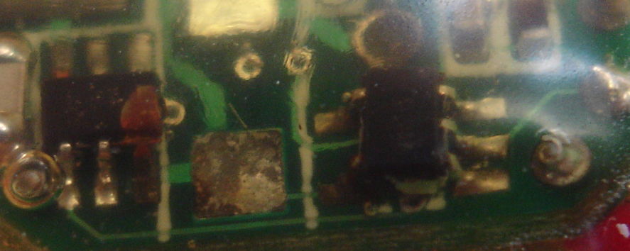
Figure: Corrosion of Pins and Pads Carrying VBAT After Nine Weeks Implanted, A3024B-R No2.1. Click for higher resolution.
In No2.1, we do see metal remaining in U2-6 and U1-5. The corrosion is a certain sign of condensation within the encapsulation, which we are familiar with from our subcutaneous transmitters. Condensation across R1, a 10-MΩ resistor, would reduce the resistance of R1, raising the device's power threshold, thus shortening its operating range.
UPDATE: [21-NOV-14] We encapsulated our Stage Four Implantable Lamps, of which No2.1 and No2.6 are two examples, in DP100 fast-curing epoxy. Its data sheet does not say that this epoxy corrodes copper, but other epoxies, such as DP270 state that they do not corrode copper, and so are recommended for encapsulation of electronic components.
No comments:
Post a Comment