Thursday, February 14, 2013

LED Efficiency

We measure the total power emitted by a selection of LEDs. To measure optical power we use an SD445 photodiode. It's sensitivity to light of various wavelengths, in Ampere per Watt, is given in the figure below. We press the photodiode right up against the package of our LED, so that is roughly 2 mm from the light-emitting surface.


We reverse-biase the photodiode with a 9-V battery and pass the photocurrent through a 100-Ω resistor. We measure the voltage across the 100-Ω resistor with a voltmeter. We convert photocurrent into optical power using the graph above. At 470 nm we use 0.20 A/W. At 527 nm we use 0.25 A/W. We provide power to the LED through a 400-Ω, 1-W resistor. We measure the LED current with an ammeter. We obtain the following plots of output power versus current.


According to the EZ290 data sheet, the minimum power output of the blue C470EZ290-021 at 20 mA forward current should be 21 mA. According to the calibration of our sample diodes, the power should be at least 27 mW for this particular LED. But we measure only 13 mW. According to the same data sheet and calibration, the green EZ290s should produce at least 11 mW at 20 mA. But we measure only 6 mW. The EZ500 data sheet, meanwhile, specifies a minimum of 40 mW of green light at forward current 150 mA. We see 26 mW at 46 mA, which suggesets of order 85 mW at 150 mA.

Our green EZ500 emits twice as much power as we expect, but our blue and green EZ290s appear to be emitting less than half the power we expected from their calibration and specification. The blue EZ290 shown above will emit only 18 mW with a forward current of 30 mA, such as we expect to deliver with our Implantable Lamp (A2024A). Even if we obtain 25% coupling efficiency into our fiber, we will get no more than 4.5 mW out of the fiber tip.

UPDATE: [26-APR-13] We have 25 C460EZ500 (460 nm blue) mounted in 3-mm packages. We measure the light power emitted by one such part with a photodiode. We bias the photodiode with 0 V and with 9 V. The photocurrent is 6% higher with bias. The responsivity of the un-biased photodiode is roughly to 0.182 for 460-nm light and 0.191 mA/mW at 470 nm.

UPDATE: [22-JAN-14] The surface of the SD445 appears to be acrylic glass, which has reflectance with angle of incidence in air as plotted below. We obtained this and the following plot from Refractive Index Info.


The silicon of the photodiode we assume to be crystalline, which has the following reflectance with angle of incidence in air. By reflection alone, we expect to lose around 44% of incident unpolarized blue light by reflection at the acrylic and silicon boundaries for light arriving perpendicular to the surface. We calculate the sensitivity of the ideal photodiode, where one photon becomes one electron, is 0.38 mA/mW for 470 nm. If we lose 44% of incoming photons by reflection, we expect our SD445 to have sensitivity 0.21 mA/mW. The data sheet says 0.20 mA/mW.


At larger angles of incidence, we will lose more light by reflection, so the sensitivity of the photodiode will drop. At 80° we expect to lose around 60% by reflection, compared to 40% at 0°, so sensitivity will drop to 0.13 mA/mW.
Monday, January 28, 2013

Antenna Matching

Today we try a split capacitor antenna matching circuit to see if we can amplify the RF signal on our antenna before presenting it to our detector diode. Such amplification is, in theory, possible, because the source impedance of the antenna signal is of order 100 Ω, this being the resistance of the antenna wire to 146 MHz, while the load impedance of our detector diode is of order 10 kΩ. We describe our analysis and testing of the split-capacitor network in detail here. The following oscilloscope trace shows the dual resonance of the matching circuit we built.


Here we see the detector diode output as a function of frequency when we have a two-loop stainless steel antenna picking up power from a nearby transmitter. The top trace is a frequency sweep voltage. The bottom trace is the detector diode output. The first peak is at 146 MHz and corresponds to a gain of 20 generated by the split capacitor tuning network. Thus the signal applied to our detector diode is twenty times larger in amplitude than the signal on our antenna. The second peak is at 170 MHz and corresponds to the resonance of the antenna inductance with our split capacitor.

We equip an Implantable Lamp (A3024) with the split capacitor circuit and test its reception when transmitting pulses of 146 MHz power at 1.6 W into a half-wave antenna. We find that reception is 100% up to range 3 m, and remains 50% at 14 m. The matching network has increased the effective range of our command receiver by a factor of six. We can now expect 100% reliable reception within a faraday enclosure at up to 1.5 m, which will be sufficient to communicate with the ISL.

Thursday, January 24, 2013

Faraday Canopy

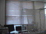
We tried out our new FE3A faraday canopy today. The photograph below shows the canopy hanging from the walls of our office. Inside you can see an implantable lamp flashing in response to power transmitted by a half-wave antenna.


The walls and ceiling are made of a transparent veil fabric woven from thin wire. The base is a layer of absorbent sheet on top of reflecting foil. For a better idea of the size and shape of the canopy, we invite you to watch the following video.


The implantable lamp is an A3024Y, which has no tuning capacitor or inductor, and is therefore sensitive to all RF frequencies. The white lamp flashes when it is within a few centimeters of our 2.4 GHz wireless router. Inside the the canopy, however, it never turns on unless we stimulate it with our own RF power. We transmit 146-MHz with a half-wave, telescoping antenna driven by a Command Transmitter (A3023CT) with booster amplifier. The booster amplifier delivers 1.6 W to the antenna and is only 10% efficient, so its black heat-sink vanes get hot to the touch.

We hold the A3024Y between thumb and forefinger and move it at random 30 cm from the transmitting antenna. We obtain 100% reliable reception. We move to range 50 cm and obtain 95% reliable reception. If we hold the A3024Y in our hand, enclosing its two-loop receiving antenna, reception at 30 cm drops to 95% and at 50 cm drops to around 80%. We expect that reception from an implanted A3034Y would be somewhere in between these two tests.

We measure the isolation provided by the canopy enclosure with respect to external interference in the 900-930 MHz range, this being the range used by our SCT system. We are hoping to find that interference power drops by a factor of one hundred within the enclosure, but instead we observe a factor of ten or twenty. For more details and discussion see here.

We are gratified to find that the ISL command transmission works just as well inside the enclosure as outside. We will work on improving the isolation the enclosure offers at the SCT data frequency. We might, for example, try adding a layer of absorber to the ceiling.

Tuesday, January 22, 2013

Implantable Lamp Encapsulation

Here is our first encapsulated Implantable Lamp (A3024Y), equipped with a BR1225 battery with capacity 48 mA-hr. This device is equipped with a white LED rather than an implantable head fixture.


The volume of the main body of the device is roughly 1.7 ml. The volume of the Subcutaneous Transmitter (A3019A), meanwhile, is 1.3 ml, and that of the Subcutaneous Transmitter (A3019D) is 2.4 ml. The former is tolerated by mice and the latter by rats. Our hope is that we can implant our 1.7-ml Implantable Lamp along with a 1.3-ml Subcutaneous Transmitter in a rat to monitor EEG and apply optical stimulus.

The A3024Y's 146-MHz command antenna is 30 mm in diameter compared to only 20 mm in diameter for the A3019A and A3019D 915-MHz data antenna. We do not know how well any animal will tolerate the larger antenna.

We move the A3024Y around at random near our 1.6-W source of 146-MHz radio-frequency power. At range 50 cm, the lamp flashes in roughly 95% of orientations. We are hoping for over 98% reliability at range 50 cm. We should be able to increase the reliability of reception by improving the tuning circuit and by increasing the power of our radio-frequency transmission.

Thursday, December 20, 2012

Command Reception

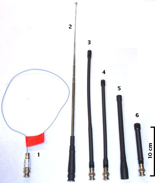
We enhance our Command Transmitter and Receiver with a Booster Amplifier (ZHL-3A+ from Minicircuits), a telescoping antenna for transmission, and a small loop antenna for reception. We describe our experiments in detail here. The figure below shows the Booster Amplifier and a selection of prototype antennas.


The figure below shows a the antennas we tested as transmitters. The one marked (2) extends to a full length of 91 cm and provides us with the most efficient transmission. It is a half-wave antenna tuned to present a 50-Ω input impedance at 146.25 MHz.


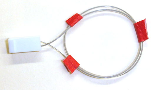
We abandoned reception antennas made out of helical steel springs. These antennas were motivated by our desire to use one of the ISL's lamp power leads as an antenna. But subsequent calculations showed that this was impractical. Our best-performing reception antenna is the two-turn loop shown below. The loop diameter is 3 cm. It is made out of silicone-insulated, stranded, stainless steel wire. We connect on end to the Command Receiver's RF input and the other end to the Command Receiver's ground potential. Unlike a quarter-wave antenna, the loop antenna picks up RF power without cooperation from the Command Receiver's ground plane. This makes its performance less dependent upon the dimensions of the Command Receiver circuit.


The booster amplifier produces 1.4 W of 146-MHz RF power. We feed this directly into the half-wave telescoping antenna and we receive it with our small, two-turn loop. We rotate and translate the Command Receiver on the end of a stick. At ranges up to 200 cm, we observe no loss of reception in any orientation. At range 300 cm, reception fails in 8% of orientations.


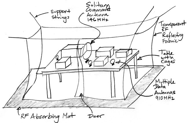
We anticipate the ISL being used on a table-top within a canopy-style Faraday enclosure, as shown above. It may be that within the reflecting walls of such an enclosure, command reception will be less reliable. It may be that implantation within an animal body will hinder reception. But we are confident that reception will be reliable at ranges up to 100 cm, and that will be good enough.

Monday, November 5, 2012

Fiber and Cannula

The ISL head fixture is supposed to hold a cannula for injections, a fiber for optical stimulation, and an electrode for EEG monitoring. In our conceptual design, we imagined a head fixture made out of plastic, as you can see here. This original fixture turns out to have several problems. The plastic body of the fixture will obstruct the surgeon's view of the skull hole, making vertical alignment difficult or impossible. The angled cannula deprives the surgeon of a vertical thread by which to hold the fixture during implantation. The proposed gold-pad grounding upon the fixture base might be covered or interfered with by the dental cement used subsequently to hold the fixture in place. To solve these problems, we propose the following, simpler head fixture.


The cannula is a C313GT or G313GFS from Plastics One, with the thread cut short. The fiber is a 330-μm outer diameter, 300-μm core silica fiber with polished base and tapered tip. The fiber is glued above a bare LED die in a 3.1-mm wide, 0.8-mm high package, which is in turn mounted on a 7-mm long 0.8-mm thick fiberglass printed circuit board. The circuit board provides a hole for the cannula. It provides footprints for isolating inductors that allow the L+ lead to be used as an RF antenna. It provides pads for two helical leads that carry L+ and L−.

The angle between the center-line of the fiber and the cannula will be roughly eight degrees, which is close to the half-angle of the fiber taper. Thus we expect the taper edge to be roughly vertical on the side closest to the cannula. When we insert a syringe down the cannula, its open end should face the fiber. By this means, whatever chemical it introduces into the brain tissue will move towards the fiber. The fiber tip will illuminate the treated tissue.

We provide the X+ electrode for monitoring local field potential with a 3-mm length of steel tube around the fiber. This tube does not extend to the base of the taper, but stops 0.5 mm short of the base, so as to allow access by the syringe to the illuminated tissue. The X- electrode will act as the EEG ground terminal. We propose a steel skull screw with a steel washer to extend its area of contact with the top of the skull.

The head fixture as shown consists of two pre-assembled parts. Part A is the fiber, LED, and printed circuit board. These we will assemble as one pice. Part B is the cannula. With the help of a mounting hole in the printed circuit board, the thread on the top of the cannula, and an adjustable assembly jig, we will align both pieces correctly. With the help of some tape and two stages of application, we will fill the gap between the fiber and cannula with epoxy for the stretch between the printed circuit board and the EEG electrode. Once glued together, parts A and B form the finished head fixture. This procedure allows for us to locate the fiber tip precisely with respect to the cannula center-line even if we encounter variations in the length of individual fibers and cannulas.

To implant the ISL head fixture, the surgeon holds it by the cannula threads and lowers it into a skull hole at least 1.6 mm in diameter. After setting the vertical position to their satisfaction, he places two skull-mounting screws nearby. He builds up dental cement around the screws and head fixture so as to bind the fixture to the screws and seal the hole in skull.

Friday, October 12, 2012

Command Transmitter-Receiver

The Command Transmitter-Receiver (A3023) is intended to test the command receiver we propose for the ISL (Implantable Sensor with Lamp) in our Conceptual Design. The A3023 is a LWDAQ Device in two parts. The Command Transmitter section contains a 146-MHz (2-m band) VCO, RF amplifier, and RF switches to provide 100% amplitude modulation. The Command Receiver section contains a tuner circuit, a demodulator, a comparator, and two indicator lamps.


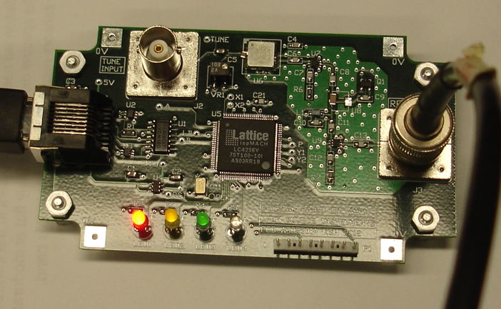
Figure: Command Transmitter. This is the left-hand side of the A302301A circuit board. This particular circuit has all components loaded except for U8, which is bypassed by a 1-μF P1206 capacitor.

The Command Transmitter provides a BNC input to modulate its VCO, a BNC output for its RF power, and a LWDAQ device socket through which we can control the two RF switches and power to the RF amplifier. The Command Receiver provides two-pin connectors for RF input, 3-V power, and binary power detector output.


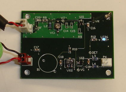
Figure: Command Receiver. Circuit power is supplied by a battery through the connector on the lower left. The RF command signal enters through the connector on the upper left. Two blue LEDs, one on the top and one on the bottom of the board, indicate when the power detector output is HI.

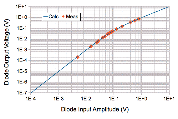
We present the results of our work with the Command Transmitter-Receiver circuit in our A3023 Manual. Here we offer a few highlights. The following graph shows the excellent agreement between our calculated and observed detector diode performance.


Figure: Detector Output versus Input Amplitude. The input amplitude is half the peak-to-peak amplitude. Measurements obtained at 8 MHz and 19°C. Calculations obtained with numerical integration.

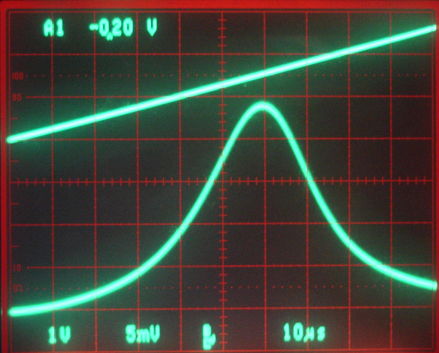
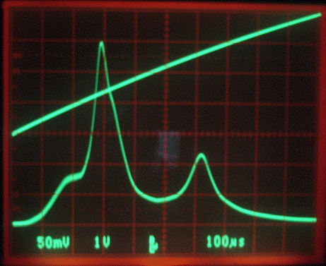
The following figure shows the performance of our 146-MHz tuning circuit. The peak is sharper than we hoped for, and the attenuation at high frequencies is greater, thus giving us better than expected rejection of the 910-MHz data frequency.


Figure: Resonance of 148-MHz Tank Circuit. The top trace is the TUNE input to the VCO, which rises from 0 V to 2.5 V, during which the frequency increases from 118 MHz to 175 MHz. The bottom trace is the detector diode output.

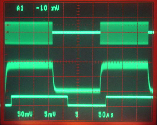
Here we see the modulation of our 146-MHz command frequency, and how it is detected with the help of a diode and a comparator in our Command Receiver.


Figure: Power Detection with 60-mV 146-MHz Input. We have C16 = 270 pF. The top trace is the RF input, 50 mV/div. Center trace is the diode output, 5 mV/div. The bottom trace is the output of the comparator. The time scale is 50 μs/div.

The Command Receiver presents one of the biggest technical challenges we describ in the ISL Conceptual Design. Our greatest concerns were the reliability of command reception at ranges up to 50 cm, rejection of data frequency power, and its current consumption while receiving 8 kbits/s. The Command Transmitter circuit is far less challenging because we have ample power and space in which to produce a modulated signal of adequate power. The receiving antenna we have little control over, because we are hoping to use one of the ISL's pick-up leads. But the transmitting antenna must be efficient, compact, and omnidirectional.

Our prototype Command Receiver consumes less than 1 μA and is effective at rejecting the maximum possible data frequency power it might receive from a nearby subcutaneous transmitter. With the prototype Command Transmitter equipped with a quarter-wave, unterminated, loop antenna, and the Command Receiver held in one hand, moving at random at range 20 cm, reception is at least 99% reliable. Given that the our prototype Command Transmitter generates only 80 mW of power for the antenna, we are confident that with 500 mW we will obtain reliable reception at 50 cm.

What remains to be determined is the performance of the command reception within a faraday enclosure. The reflecting surfaces of the faraday enclosure produce reception dead spots, and the absorbers present in our existing enclosures are less effective at 146 MHz. We are confident, however, that we can overcome the effect of internal reflections by suitable design of the antenna and addition of different absorbers.

One thing we must accept, however, is that command reception cannot be 100% reliable. It might be 99% reliable, but we must still be prepared to lose some commands, and we must be able to tolerate corrupted commands. Thus we expect to add a cyclic redundancy check to the command transmission protocol, and a means by which the ISL can inform the control system that commands have gone missing.