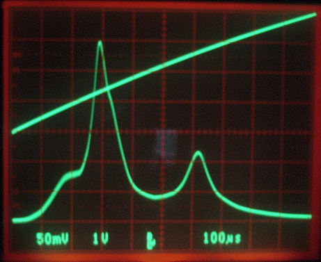
Here we see the detector diode output as a function of frequency when we have a two-loop stainless steel antenna picking up power from a nearby transmitter. The top trace is a frequency sweep voltage. The bottom trace is the detector diode output. The first peak is at 146 MHz and corresponds to a gain of 20 generated by the split capacitor tuning network. Thus the signal applied to our detector diode is twenty times larger in amplitude than the signal on our antenna. The second peak is at 170 MHz and corresponds to the resonance of the antenna inductance with our split capacitor.
We equip an Implantable Lamp (A3024) with the split capacitor circuit and test its reception when transmitting pulses of 146 MHz power at 1.6 W into a half-wave antenna. We find that reception is 100% up to range 3 m, and remains 50% at 14 m. The matching network has increased the effective range of our command receiver by a factor of six. We can now expect 100% reliable reception within a faraday enclosure at up to 1.5 m, which will be sufficient to communicate with the ISL.
No comments:
Post a Comment