
Figure: ISL Stage Four Delivery of Implantable Lamp Circuits, A3024B-M and A3024B-R. The blue line is 50 mm long.
The operating range of these lamps for command reception in our basement office is at least three meters. But one of our concerns with the mouse-sized A3024B-M is the size of the antenna, combined with the short length of the leads. We are not sure how the surgeon can implant this device in a mouse with the antenna maintaining its shape and the leads reaching the skull. If the surgeon finds that there is insufficient space to accommodate the antenna as it is, he should feel free to deform its shape. Deformation of the antenna will reduce operating range for command reception, but we expect the range will still be over 100 cm.
The table below lists the characteristics of each lamp. We estimate the transmitter volume from caliper measurements. We charged the batteries just before encapsulation. We measure the lead resistance with a meter. The current delivered by a lamp circuit is limited by the resistance of its leads. Lamp circuit No2.4 has two solder joints in its leads at the base, where we replaced unstretched leads with stretched leads to allow the circuit to deliver more current.
| Circuit Number | Battery Capacity | Body Volume | Lead Length | Lead Type | Lead Resistance |
|---|---|---|---|---|---|
| 2.1 | 160 mAhr | 4.8 ml | 100 mm | Stretched | 56 Ω |
| 2.2 | 19 mAhr | 1.7 ml | 50 mm | Unstretched | 55 Ω |
| 2.3 | 19 mAhr | 1.7 ml | 50 mm | Unstretched | 55 Ω |
| 2.4 | 19 mAhr | 1.7 ml | 50 mm | Stretched | 29 Ω |
| 2.6 | 160 mAhr | 4.8 ml | 100 mm | Stretched | 56 Ω |
The photograph below shows one of five A3024HFB head fixtures. There is some deliberate variation in the way we aligned the fiber tip and the guide cannula. Click on the head fixture names to get a close-up picture of each one. In all cases, the fiber's outer diameter is close to 450 μm. The head fixture shown below is No2.11, an A3024HFB-G green lamp. Note that the glue does not extend to the contact between the guide cannula and the taper. In some head fixtures, the contact point is glued, in others it is not. In the former, we are sure there is no glue on the taper. In the later, we know that the guide cannula is fragile. We are also shipping A3024HFB-B No2.4, 2.9, 2.6, and A3024HFB-G No2.12. All are equipped with two sockets that accept 300-μ diameter pins. the L+ connection is marked "+" on the circuit board, and the L− connection is marked "−".
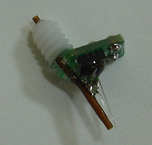
Figure: ISL Stage Four Head Fixture A3024HFB-G. The guide cannula is 15 mm long, and designed for a 22-gague needle. It is PlasticsOne part C313GS-4-FS-SP. The cannula ends 9 mm below the pedestal.
The characteristics of each head fixture are given in two tables for the blue and green versions. Any implantable lamp may be combined with any head fixture. By choosing which lamp circuit to combine with which head fixture, we can obtain more or less power at the fiber tip, and more or less operating life. The following table shows some example combinations.
| Circuit Number | Battery Capacity | Lamp Number | Light Power | Light Color | Lamp Current | 100% Duty Life | 10% Duty Life |
|---|---|---|---|---|---|---|---|
| 2.4 | 19 mAhr | 2.4 | 22 mW | Blue | 70 mA | 5 min | 2 hrs |
| 2.6 | 160 mAhr | 2.12 | 6 mW | Green | 40 mA | 2 hr | 20 hrs |
| 2.2 | 19 mAhr | 2.9 | 13 mW | Blue | 42 mA | 10 min | 3 hrs |
If the capacity of a lithium-ion battery is C mA-hr, it can deliver up to C mA continuously while delivering its full capacity. At higher currents, its capacity decreases. But if it is allowed to recover after short bursts of higher current, it can deliver close to its full capacity. We present discharge graphs for our lamp circuit batteries here.
According to Bernstein et al., "To activate channelrhodopsin-2 and halorhodopsin molecules in mammalian neurons requires light of the appropriate color at a radiant flux of 10 mW/mm2 or greater, for maximal activation. A radiant flux of 1 mW/mm2 will activate approximately 50% of the molecules, and a radiant flux of 0.1 mW/mm2 will activate very few of the molecules." Light power density will drop with range from our fiber tip due to the geometric inverse square law, scattering, and absorption. Scattering causes power loss only because it encourages absorption by increasing the effective path length from the fiber tip. According to Johansson, the absorption coefficient of brain tissue is 0.35 mm−1 at 460 nm and 0.25 mm−1 at 527 nm. The scattering coefficient is around 1.2 mm−1 for both wavelengths.
Along a 1-mm path in the brain, 70% of photons will be scattered. Most of them will travel around 1.5 mm to arrive 1 mm from their starting point. Along this 1.5 mm path, 40% of 460-nm photons and 30% of 527-nm photons will be absorbed. If we consider a hemisphere around the base of our fiber tip, of radius 1 mm, its area is 2π mm2. If the fiber tip emits 13 mW of 460-nm light, the intensity on the surface of this hemisphere will be of order 13 mW / 2π mm2 × 60% = 1.2 mW/mm2. For 6 mW of green light we get 0.67 mW/mm2 at the same range. Our calculation is optimistic in that we assume the light is confined only to a hemisphere, but pessimistic because it ignores the fact that the light is being emitted all along the fibre tip, so the path length of most photons to the hemisphere surface will be shorter than we have assumed.
Thus we believe that our head fixtures can deliver over 1 mW/mm2 of 460 nm light and over 0.5 mW/mm2 of 527 nm light at a range of 1 mm from the fiber tip, and that this intensity will be sufficient to excite a significant proportion of opsin molecules in a 1-mm hemisphere.