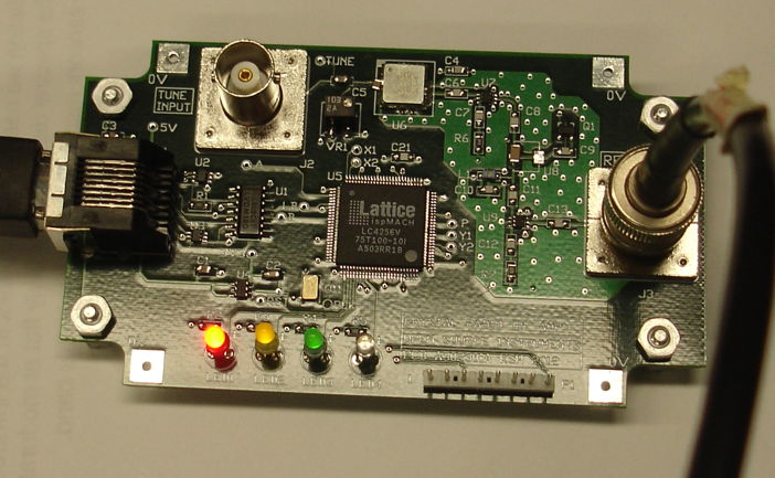
Figure: Command Transmitter. This is the left-hand side of the A302301A circuit board. This particular circuit has all components loaded except for U8, which is bypassed by a 1-μF P1206 capacitor.
The Command Transmitter provides a BNC input to modulate its VCO, a BNC output for its RF power, and a LWDAQ device socket through which we can control the two RF switches and power to the RF amplifier. The Command Receiver provides two-pin connectors for RF input, 3-V power, and binary power detector output.
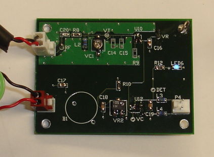
Figure: Command Receiver. Circuit power is supplied by a battery through the connector on the lower left. The RF command signal enters through the connector on the upper left. Two blue LEDs, one on the top and one on the bottom of the board, indicate when the power detector output is HI.
We present the results of our work with the Command Transmitter-Receiver circuit in our A3023 Manual. Here we offer a few highlights. The following graph shows the excellent agreement between our calculated and observed detector diode performance.
Figure: Detector Output versus Input Amplitude. The input amplitude is half the peak-to-peak amplitude. Measurements obtained at 8 MHz and 19°C. Calculations obtained with numerical integration.
The following figure shows the performance of our 146-MHz tuning circuit. The peak is sharper than we hoped for, and the attenuation at high frequencies is greater, thus giving us better than expected rejection of the 910-MHz data frequency.
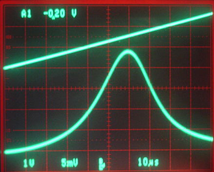
Figure: Resonance of 148-MHz Tank Circuit. The top trace is the TUNE input to the VCO, which rises from 0 V to 2.5 V, during which the frequency increases from 118 MHz to 175 MHz. The bottom trace is the detector diode output.
Here we see the modulation of our 146-MHz command frequency, and how it is detected with the help of a diode and a comparator in our Command Receiver.
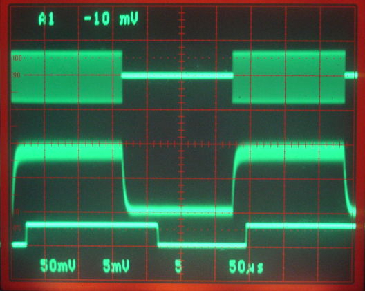
Figure: Power Detection with 60-mV 146-MHz Input. We have C16 = 270 pF. The top trace is the RF input, 50 mV/div. Center trace is the diode output, 5 mV/div. The bottom trace is the output of the comparator. The time scale is 50 μs/div.
The Command Receiver presents one of the biggest technical challenges we describ in the ISL Conceptual Design. Our greatest concerns were the reliability of command reception at ranges up to 50 cm, rejection of data frequency power, and its current consumption while receiving 8 kbits/s. The Command Transmitter circuit is far less challenging because we have ample power and space in which to produce a modulated signal of adequate power. The receiving antenna we have little control over, because we are hoping to use one of the ISL's pick-up leads. But the transmitting antenna must be efficient, compact, and omnidirectional.
Our prototype Command Receiver consumes less than 1 μA and is effective at rejecting the maximum possible data frequency power it might receive from a nearby subcutaneous transmitter. With the prototype Command Transmitter equipped with a quarter-wave, unterminated, loop antenna, and the Command Receiver held in one hand, moving at random at range 20 cm, reception is at least 99% reliable. Given that the our prototype Command Transmitter generates only 80 mW of power for the antenna, we are confident that with 500 mW we will obtain reliable reception at 50 cm.
What remains to be determined is the performance of the command reception within a faraday enclosure. The reflecting surfaces of the faraday enclosure produce reception dead spots, and the absorbers present in our existing enclosures are less effective at 146 MHz. We are confident, however, that we can overcome the effect of internal reflections by suitable design of the antenna and addition of different absorbers.
One thing we must accept, however, is that command reception cannot be 100% reliable. It might be 99% reliable, but we must still be prepared to lose some commands, and we must be able to tolerate corrupted commands. Thus we expect to add a cyclic redundancy check to the command transmission protocol, and a means by which the ISL can inform the control system that commands have gone missing.