We ship to ION the devices shown below. There are five Implantable Sensors with Lamp (
A3030C), five Head Fixtures (
A3024HFC-B), a 915-MHz Command Transmitter (
A3029B), a Loop Antenna (
A3015C) for command transmission, and various cables and connectors.

Figure: Batch ISL6 Deliverables. The five encapsulated A3030Cs are on the center right. For a close-up see here. The ISLs are encapsulated in black epoxy and clear silicone. On the left we have antenna cable, LWDAQ cable, and boost power supply for the command transmitter, which is itself the square metal box. We have three BNC feedthroughs to enhance an existing faraday enclosure. Five head fixtures are arranged in petri dishes below.
Each ISL provides a 50-mm 915-MHz command antenna and a separate 50-mm 915-MHz data and acknowledgement antenna. Command reception by a moving ISL in a faraday enclosure at 915 MHz is >95%, compared to less than 10% with our previous 146-MHz command frequency. We will perform more exhaustive tests of reception at 915 MHz in the near future. The A3030C can respond to commands with an acknowledgement on the 915 MHz auxiliary data channel, without disturbing or requiring simultaneous data transmission. Version 3 of the
ISL Controller Tool allows us to detect acknowledgements collected by the Recorder Instrument.
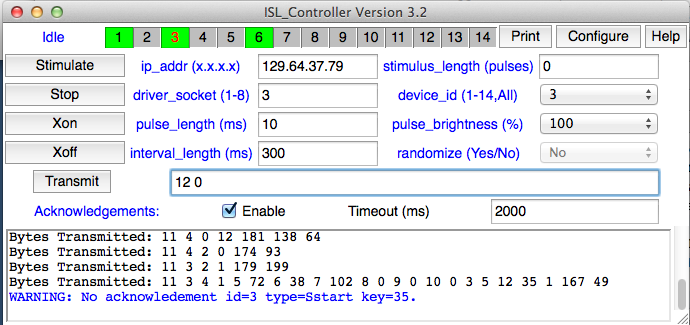
Figure: ISL Controller Tool, Version 3. To receive acknowledgements from ISLs, the Recorder Instrument must be acquiring messages, either with the Loop command in the instrument itself, or the Record command in the Neuroarchvier.
The lamp leads are orange (L+) and purple (L−). They are held together with silicone so as to reduce the magnetic field they generate when the lamp current turns on. The EEG leads are red (X+) and blue (X−). These are held together with silicone so as to reduce the magnetic field they enclose when the lamp current turns on. The input impedance of the A3030C amplifier is only 100 kΩ, compared to 10 MΩ in previous devices. These precautions together reduce the amplitude of the spikes induced by lamp current.

Figure: Lamp Current and Voltage Noise on X for A3030C with Lamp Pins Above Water, White LED Attached, and Lamp and EEG Leads Running Close Together. Pulses of 100 ms every 200 ms.
With the A3030B, the above arrangement of the ISL in water produced voltage spikes much larger than the 20-mV range of the EEG amplifier. The noise spikes are now of order 200 μV. We appear to have reduced the induced noise amplitude by a factor of one hundred. We see a square wave much larger than 20 mV if we immerse the lamp power pins in the same water as the EEG pick-up leads. During implantation, we must make sure that there is electrical isolation between the lamp pins and the rat's body. The pins should be entirely covered with insulating cement.
Outside the light pulses, there should be no noise induced upon the EEG input because the A3030C turns off its boost regulator between pulses. During the light pulses, after the initial spike when the lamp turns on, we see the same 8 μV amplifier-generated noise we see outside the pulses. Because of the way it manages its power consumption when idle, the boost regulator generates less noise when it is delivering a continuous current than it does when it is delivering no current at all. Thus we see noise spikes only at the start and finish of each light pulse.
One feature does remain in the EEG recording during and after pulses: a relaxation in response to the step-component of the lamp current noise, rather than its pulse component. We cover the LED so its light does not land on the water near our EEG electrodes, and the step-component of the lamp current noise remains unchanged. It is not a photovoltaic effect. When the lamp power turns on, the lamp current leads now carry +5V and 0V instead of both carrying 0V. Despite the insulation around the lamp leads, this change affects the potential of the ISL body, and so induces a step change in the EEG amplifier input of order 50 μV, which then relaxes in response to the amplifier's high-pass filters. With shorter pulses, such as those shown on the same scale below, the steps cannot be seen.
Figure: Lamp Current and Voltage Noise on X for A3030C with Lamp Pins Above Water, White LED Attached, and Lamp and EEG Leads Running Close Together. Pulses of 10 ms every 100 ms.
The A3024HFC-B head fixtures are all equipped with blue LEDs. We measure power at the tip of the fiber to be 13-16 mW at 40-mA forward current. The average is 14.5 mW. The forward voltage drop of the LEDs is 2.8 V, we have 5-V lamp power, and the lamp leads have resistance 60 Ω. When implanted, the current will be 36 mA, so we expect power at the tip to be 13 mW. This power is sufficient to provoke optogenetic response with 5-ms flashes at 10 Hz.
When the lamp is on, the A3030C draws roughly 60 mA from its 190 mA-hr battery. Stimulating with 5-ms flashes at 10 Hz, the battery can run for 76 hours. With the internal state machines running, but no data transmission or lamp stimulation, the A3030C consumes only 60 μA. Allowing for one hour of stimulation per day, it should be possible to run a 60-day experiment with the A3030C.
The goals of ISL6 were to provide reliable command reception inside our 915-MHz enclosures, and to reduce the lamp-current noise induced in the EEG input. We look forward to seeing how well the devices perform when implanted.
